Transmission Lines
Distributed-Parameter Model
Section titled “Distributed-Parameter Model”A transmission line guides electromagnetic energy from a source to a load. The distributed model describes structures such as a wire pair, coaxial cable, stripline, and, approximately, microstrip; hollow waveguides require mode-dependent propagation models.
-
Distributed parameters: Resistance, inductance, capacitance, and leakage conductance occur along the entire line. Voltage and current therefore depend on position as well as time.
-
Electrical length: A lumped model becomes inadequate when propagation delay is appreciable compared with the sinusoidal period or a digital signal’s rise time. A length of about is a common sinusoidal guideline, not a sharp boundary.
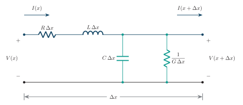
Equivalent circuit of a transmission-line section.
Primary Constants
Section titled “Primary Constants”| Constant | Unit | Physical origin | Element in length |
|---|---|---|---|
| Conductor loss, including frequency-dependent skin effect | Series resistance | ||
| Magnetic field associated with line current | Series inductance | ||
| Electric field between conductors | Shunt capacitance | ||
| Leakage and dielectric loss | Shunt conductance |
Telegrapher Equations
Section titled “Telegrapher Equations”Take from source to load and reference current in the direction. Use sinusoidal phasors with time factor . To first order in , KVL across the series elements and KCL through the shunt elements give:
KVL:
KCL:
Limit form:
Wave equations:
Propagation constant:
Secondary Constants
Section titled “Secondary Constants”| Quantity | Meaning | Unit or relation |
|---|---|---|
| Complex propagation constant | ||
| Exponential attenuation per unit length | ||
| Phase change per unit length | ||
| Characteristic impedance | ||
| Phase velocity at the stated frequency | ||
| Distance for a phase change |
A forward wave’s amplitude falls by a factor over length . Its one-way attenuation in decibels is
Lossless Line
Section titled “Lossless Line”For ,
Low-Loss and Distortionless Lines
Section titled “Low-Loss and Distortionless Lines”For and ,
An idealised distortionless line satisfies the Heaviside condition
Under this condition, with frequency-independent parameters,
Characteristic Impedance
Section titled “Characteristic Impedance”-
Wave ratio: Characteristic impedance is the voltage-to-current ratio of a single forward travelling wave.
-
Input impedance: An infinitely long uniform line has input impedance because no wave returns from its far end. A finite uniform line terminated in has the same input impedance.
For a forward wave, :
For a lossy line, is generally complex and frequency-dependent. For a lossless line, it reduces to .
Matched Termination
Section titled “Matched Termination”-
No reflection: With , the incident wave already satisfies the load’s voltage-to-current ratio. No reflected wave is required, and the line’s input impedance is at any length.
-
Source matching: Eliminating load reflection is distinct from maximising power drawn from a source. Maximum available source power requires a conjugate match at the source port; the source impedance and any intervening matching network must also be considered.
Incident and Reflected Waves
Section titled “Incident and Reflected Waves”An impedance discontinuity generates a reflected wave that travels toward the source. For a uniform line from to , with current referenced in the direction, the total voltage and current are the sums of forward and backward waves.
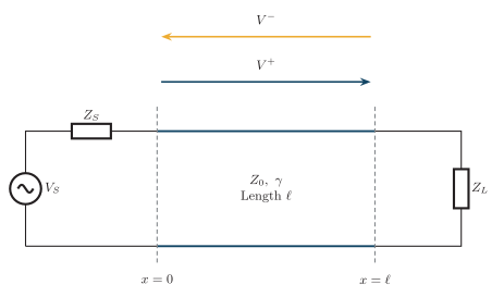
Incident and reflected waves on a terminated transmission line.
and are the wave amplitudes at . The reflected-current term has a minus sign because both currents use the same reference, while the reflected wave carries energy in the opposite direction.
Load Reflection Coefficient
Section titled “Load Reflection Coefficient”Let and be the incident and reflected voltage-wave amplitudes at the load. Their total voltage and current must satisfy the load impedance:
With :
is dimensionless and generally complex. Its magnitude is the reflected-to-incident voltage amplitude ratio; its angle is the reflected wave’s phase relative to the incident wave at the load.
At distance from load toward source:
The factor 2 accounts for travel to the load and back. On a lossless line, moving the reference plane changes only the phase of ; on a lossy line, its magnitude toward the source decreases by .
Matched, Open and Short Circuits
Section titled “Matched, Open and Short Circuits”| Termination | Voltage at load | Current at load | |
|---|---|---|---|
| Incident voltage only | Incident current only | ||
| Open circuit | Incident and reflected voltages add | Incident and reflected currents cancel | |
| Short circuit | Incident and reflected voltages cancel | Incident and reflected currents add |
Standing Waves and VSWR
Section titled “Standing Waves and VSWR”-
Standing waves: Interference between incident and reflected waves creates stationary maxima and minima in the voltage envelope along the line.
-
VSWR: The ratio of maximum to minimum voltage amplitude measures mismatch on a lossless line. A matched line has a uniform envelope and VSWR of 1.
For a lossless line,
The voltage standing-wave ratio is
Therefore,
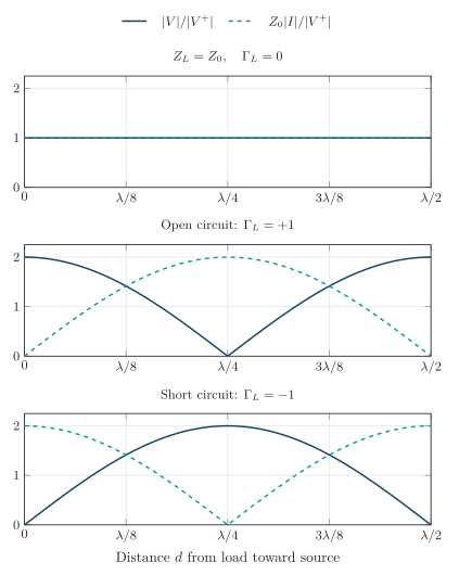
Voltage and current standing waves for matched, open and shorted lines.
-
Voltage maxima are separated by , and voltage minima are separated by .
-
A voltage maximum and its nearest voltage minimum are separated by .
-
On a lossless line, a voltage maximum coincides with a current minimum and vice versa.
-
At an open load, voltage is maximum and current is zero; at a shorted load, voltage is zero and current is maximum.
-
A matched lossless line has uniform voltage/current amplitudes and ; complete reflection gives .
Return Loss and Reflected Power
Section titled “Return Loss and Reflected Power”Return loss compares incident and reflected power at the same reference plane. For a real, positive reference impedance , the reflected power fraction is , giving
Useful relationships:
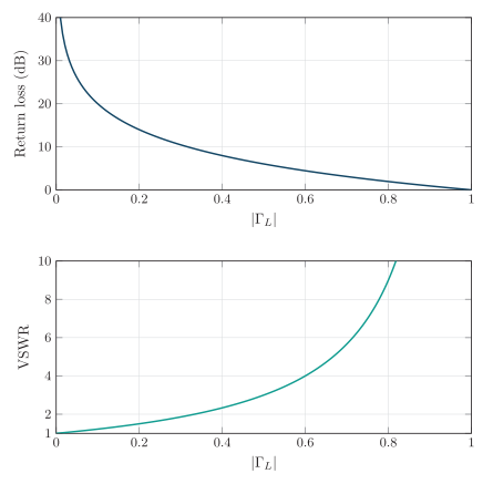
Variation of return loss and VSWR with reflection coefficient.
| Condition | VSWR | Return loss | Reflected power | |
|---|---|---|---|---|
| Perfect match | ||||
| Good match example | ||||
| Moderate mismatch | ||||
| VSWR of 2 | ||||
| Open or short |
Input Impedance
Section titled “Input Impedance”For a uniform line of length terminated in ,
For a lossless line, and , giving
| Lossless-line condition | Input impedance |
|---|---|
| Matched load | |
| Short-circuited load | |
| Open-circuited load | |
| Half-wavelength line | |
| Quarter-wavelength line |
Impedance Matching
Section titled “Impedance Matching”Impedance matching reduces reflections, standing waves, and power returned to the transmitter. By limiting repeated reflections, it also reduces response ripple and reflection-related echo.
| Method | Principle | Main limitation |
|---|---|---|
| Matched termination | Set the terminating impedance equal to the line’s | Dissipates received power in the terminating load |
| Transformer | Reflect impedance through the square of the turns ratio | Practical bandwidth, loss and parasitics |
| Quarter-wave section | Transform a real resistance using a specified line impedance and electrical length | Frequency-sensitive; simplest form matches real resistances |
| Reactive network or stub | Cancel reactance and transform the resistive part | Frequency dependence and tuning requirements |
Quarter-Wave Transformer
Section titled “Quarter-Wave Transformer”A lossless section of characteristic impedance and length transforms a real load resistance into
To match it to a line of real characteristic impedance ,
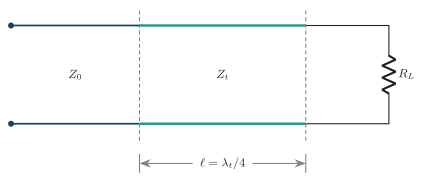
Quarter-wave impedance transformer.
Worked Problems
Section titled “Worked Problems”Lossless Line Constants
Section titled “Lossless Line Constants”A lossless line has , , and . At , find , , , and .
Lossy Line from RLCG
Section titled “Lossy Line from RLCG”At , a line has , , and .
Using the passive-line square-root branch,
Thus , , and . The one-way travelling-wave attenuation over 100 m is
Real Load Mismatch
Section titled “Real Load Mismatch”A lossless line is terminated in .
For incident power , the reflected power is and the load receives .
Complex Load Mismatch
Section titled “Complex Load Mismatch”A lossless line is terminated in .
The reflected power fraction is . Both VSWR and return loss depend on the magnitude of the complex reflection coefficient, not its real part alone.
Return Loss from VSWR
Section titled “Return Loss from VSWR”A lossless line has . Its reflection magnitude and return loss are
Quarter-Wave Matching
Section titled “Quarter-Wave Matching”Match a load to a line at using a lossless quarter-wave section. The section’s phase velocity is . Its required impedance and length are
At the design frequency,
so the section presents to the main line at the design frequency.