Digital Display
Seven-Segment Construction
Section titled “Seven-Segment Construction”A seven-segment display contains seven individually controlled LED bars, labelled through , arranged as a figure eight. An optional decimal point is labelled .
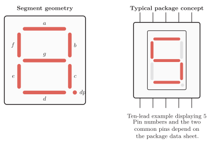
Seven-segment lettering and package concept.
Each segment is an LED and requires correct polarity and current limiting. Segment names are standardized; package pin numbers, forward voltage and current ratings are not, so use the actual data sheet.
| Digit | BCD | |||||||
|---|---|---|---|---|---|---|---|---|
Decimal digit patterns (1 means illuminated).
This table describes light, not electrical pin level. Common-anode displays require the complemented electrical commands.
Common Cathode and Common Anode
Section titled “Common Cathode and Common Anode”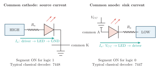
One illuminated segment in common-cathode and common-anode displays.
| Feature | Common cathode (CC) | Common anode (CA) |
|---|---|---|
| Common terminal | Cathodes to ground | Anodes to |
| Segment ON command | HIGH at segment anode | LOW at segment cathode |
| Driver action | Sources current | Sinks current |
| Electrical polarity | Active HIGH | Active LOW |
| Classical decoder | ||
| Digit selector | Low-side NPN/NMOS | High-side PNP/PMOS |
Common-cathode and common-anode displays.
Use one resistor in each segment line. A resistor only in the common lead makes current and brightness depend on how many segments are illuminated.
Segment Driving
Section titled “Segment Driving”For a static segment drive,
For a sinking output, use its LOW voltage for . For a sourcing output, use the actual loss between and the guaranteed HIGH level. Choose the next larger standard resistance, then check and the driver’s per-pin and total-current limits.
Use a transistor or driver IC when one logic output cannot safely provide the required segment current. Never exceed the LED’s continuous or pulsed-current rating.
BCD-to-Seven-Segment Decoding
Section titled “BCD-to-Seven-Segment Decoding”A decoder accepts BCD input , with the most-significant bit, and generates seven segment commands. For example, selects .
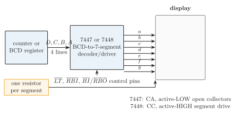
BCD decoder/driver signal chain and auxiliary controls.
| Device | Output/display | Important point |
|---|---|---|
| Active-LOW open-collector outputs for common anode | Sinks current; external segment resistors required | |
| Active-HIGH drive for common cathode | Source capability depends on the exact family version |
Classical BCD-to-seven-segment drivers.
The usual auxiliary controls are active LOW:
-
: lamp test turns all segments on;
-
: blanking input turns all segments off;
-
and : suppress leading or trailing zeros across several digits.
Codes 1010–1111 are invalid BCD inputs; their display pattern is unspecified unless the chosen decoder defines or blanks it.
Multiplexed Multi-Digit Display
Section titled “Multiplexed Multi-Digit Display”Multiplexing shares the seven segment buses and enables one digit common at a time. An -digit display then uses about principal control lines instead of .
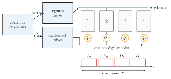
Four-digit multiplexing with a shared segment bus and one-hot scan.
For equal slots,
The frame rate must avoid visible flicker. Peak current must stay within LED, segment-driver and digit-driver pulse ratings. Use break-before-make scanning: disable the old digit, change segment data, then enable the new digit. This prevents ghosting.