Safety: Shock, Earthing, Shielding and Lightning
Earthing (Grounding)
Section titled “Earthing (Grounding)”Earthing connects non-current-carrying metal parts (chassis, racks, towers, shields) to the mass of earth through a low-resistance conductor, so fault, leakage, static and lightning currents are safely discharged.
Objectives: (1) personnel shock safety; (2) equipment protection; (3) fast operation of fuses/breakers/ELCB; (4) lightning discharge; (5) common zero-potential reference (less EMI/hum/crosstalk); (6) static drain.
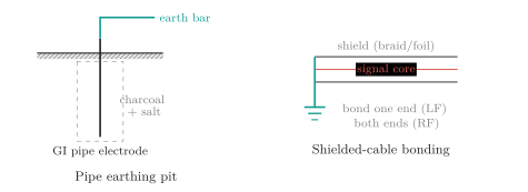
Earth electrode in treated soil, and shield bonding (one end for low-frequency signals to avoid a ground loop; both ends for RF).
| Type | Construction | Use |
|---|---|---|
| Plate | Cu/GI plate () deep in charcoal+salt | Substations, high fault current |
| Pipe | GI pipe (, 2.5 m) with charcoal+salt | Most common; buildings, exchanges |
| Rod | Cu / Cu-bonded steel rods driven in | Rocky/sandy soil; quick install |
| Strip / wire | GI strip or wire in horizontal trenches | Line towers, hilly areas |
| Chemical | Electrode with conductive backfill | Sites needing a stable low |
Earthing construction types.
| Function | Purpose |
|---|---|
| Protective (safety) earth | Equipment body/chassis earthing for shock safety |
| System / signal earth | Reference for DC power ( V return) and signals |
| Lightning earth | Dedicated down-conductor path from the air terminal |
| Ring (equipotential) earth | Buried ring bonding all electrodes together |
Earthing by function at a telecom site.
Shielding
Section titled “Shielding”A grounded conductive barrier (braid, foil, enclosure) intercepts EMI/RFI and drains it to earth: it blocks external interference, prevents cross-talk between pairs, protects low-level signals and cuts radiated emissions. The shield must be bonded (a floating shield re-radiates noise): a low-frequency signal cable is usually bonded at one end to avoid a ground loop, whereas RF/coaxial shields need bonding at both ends. Shielding never replaces the protective-earth conductor.
| Earthing / bonding | Shielding | |
|---|---|---|
| Purpose | Shock safety, fault/lightning path, equipotential | Reduce EMI/RFI, crosstalk, emissions |
| Normal current | Ideally none in the PE | May carry induced/common-mode current |
| Key feature | Continuous low-impedance electrode/loop | Continuous coverage, correct termination |
Earthing versus shielding: different jobs, coordinated by equipotential bonding.
Lightning Protection
Section titled “Lightning Protection”Lightning (10–200 kA, microseconds) damages telecom plant by direct strike, induced surge, ground-potential rise, and conducted surge on mains/lines/coax. Protection is a coordinated system that intercepts, conducts, disperses, equalises and limits.
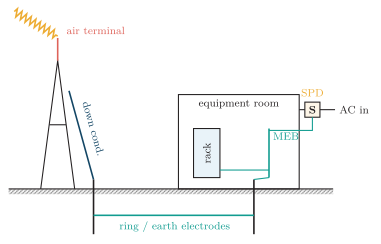
Complete telecom-site protection: air terminal and down conductor to a ring earth, single equipotential earth (MEB) bonding rack/shields, and SPDs on incoming services.
Current path: air terminal (rolling-sphere zone) short, straight down conductor low-impedance earth termination (tower-leg electrodes buried ring) equipotential bonding of tower/racks/trays/PE to a master earth bar single-point cable entry (bond armour/shields) coordinated power SPDs plus GDTs on line pairs and arrestors on RF feeders.
Surge Protectors, Fuses and Circuit Breakers
Section titled “Surge Protectors, Fuses and Circuit Breakers”A surge protective device (SPD) sits in parallel with the load: high impedance normally, low impedance during a transient, diverting the impulse and clamping the downstream voltage. It must satisfy and .
| Device | Principle | Features |
|---|---|---|
| MOV | Voltage-dependent ZnO clamp | Fast, high energy; degrades with surges |
| GDT | Gas ionises/arcs at spark-over | Very high current, slower; line pairs |
| TVS diode | Semiconductor precise clamp | Very fast (ps–ns), low energy; boards |
| Spark gap | Air/ceramic flashover | Heavy-duty power-entrance protection |
SPD technologies (energy: GDT MOV TVS; speed: TVS MOV GDT).
| Class | Location | Handles |
|---|---|---|
| I (Type 1) | Service entry / LPS | Direct lightning current (s) |
| II (Type 2) | Sub-distribution board | Induced surges (s) |
| III (Type 3) | At the equipment socket | Residual let-through voltage |
SPD classes coordinated by installation zone (I II III).
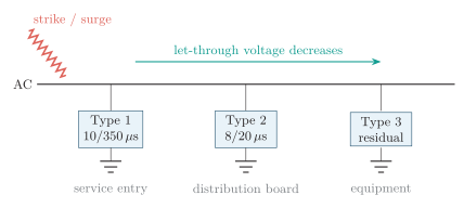
Coordinated SPD protection: a Type 1 device at the service entry diverts partial direct-lightning current, a Type 2 device at the distribution board clamps induced surges, and a Type 3 device limits the residual let-through voltage at the equipment.
A fuse is a sacrificial series device whose element melts on overcurrent; its let-through stress is . A circuit breaker is a resettable series device (thermal inverse-time overload magnetic instantaneous short-circuit trip).
| Breaker | Principle / use |
|---|---|
| MCB | Thermal magnetic; final circuits () |
| MCCB | Higher, adjustable ratings; distribution boards |
| ELCB / RCCB / RCD | Trips on residual (leakage) current — shock protection |
| ACB | Large LV switchboards |
| VCB / | Vacuum / gas arc-quench — HV substations |
Circuit-breaker types.
| Feature | Fuse | Circuit breaker |
|---|---|---|
| Operation | Element melts (one-time ) | Thermal/magnetic trip (resettable) |
| Restoration | Replace with correct type | Reset/reclose after inspection |
| Functions | Overcurrent only | Overload, short-circuit; RCD: leakage |
| Breaking capacity | Very high (HRC) | Select rated Icu/Ics |
| Control | None | Trip indication, remote operation |
Fuse vs circuit breaker. Both need breaking capacity prospective fault current.