Analog Modulation
Need for Modulation
Section titled “Need for Modulation”Modulation is the controlled variation of a parameter of a high-frequency carrier by a lower-frequency message. Varying amplitude gives AM, frequency gives FM and phase gives PM.
| Carrier parameter varied | Modulation |
|---|---|
| Amplitude | AM |
| Frequency | FM |
| Phase | PM |
Reasons for modulation.
-
Practical antenna size: efficient radiation needs a dimension with . A 3 kHz tone gives , i.e. a quarter-wave — impractical, so the message is translated up to RF.
-
Bandpass channel matching: antennas, microwave links, satellite transponders and AC-coupled circuits work only over assigned nonzero bands.
-
Frequency allocation: different stations use different carriers so a tuned receiver can select one.
-
Multiplexing: FDM places several messages on separate carriers in one medium.
-
Propagation choice: translation permits a band with suitable antenna gain, spectrum and propagation for the link.
-
Noise/interference planning: carrier placement enables filtering and a modulation with suitable immunity.
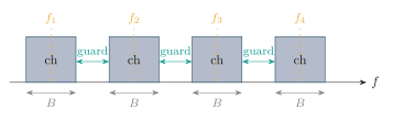
Frequency-division multiplexing: baseband channels are stacked in adjacent carrier bands with guard bands between them.
Modulation does not by itself remove noise or guarantee greater range; the best carrier depends on regulation, propagation, antenna gain and power.
Standard Amplitude Modulation (AM)
Section titled “Standard Amplitude Modulation (AM)”In standard full-carrier AM the carrier amplitude varies linearly with the message, while carrier frequency and phase stay constant.
Single-Tone Derivation
Section titled “Single-Tone Derivation”With and :
The spectrum has a carrier at (amplitude ), a USB at and a LSB at (each amplitude ).
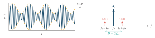
Standard AM with : time waveform and envelope (top), then its single-tone spectrum with carrier and sidebands at (bottom).
Modulation Index
Section titled “Modulation Index”| Condition | Index | Envelope |
|---|---|---|
| Under-modulation | Faithful, nonzero | |
| Critical / 100% | Just reaches zero | |
| Overmodulation | Crosses zero; diode detection distorts |
For a general message the no-overmodulation limit is .
Bandwidth and Power
Section titled “Bandwidth and Power”If the message occupies , the sidebands span :
The carrier carries most of the power but no unique information; for a real message both sidebands are duplicates.
Generation/detection overview. Low-level AM modulates at low power then linearly amplifies; high-level AM modulates the final PA. An envelope detector (diode–) suffices for ; a synchronous product detector gives better linearity and noise performance.
Double Sideband Suppressed Carrier (DSB-SC)
Section titled “Double Sideband Suppressed Carrier (DSB-SC)”DSB-SC transmits both sidebands but suppresses the carrier:
Bandwidth stays ; all transmitted power is in the information-bearing sidebands; coherent detection is required.
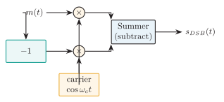
Balanced modulator: two AM modulators fed by and share a common carrier; subtracting the outputs cancels the carrier and leaves the product .
Practical product modulators use balanced transistor or diode multipliers so symmetry cancels carrier feedthrough. A double-balanced diode-ring modulator suppresses both carrier and message feedthrough ideally, leaving the desired sum-and-difference products that form DSB-SC.
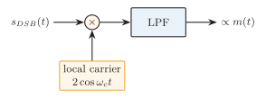
Coherent (product) detector: multiply the received signal by a synchronized local carrier and low-pass filter to recover .
Multiplying by and low-pass filtering gives : an envelope detector fails because the DSB-SC envelope is and loses the sign of . Phase error costs ; frequency error causes beating.
Single Sideband Suppressed Carrier (SSB-SC)
Section titled “Single Sideband Suppressed Carrier (SSB-SC)”SSB transmits only one sideband (usually carrier-suppressed). With Hilbert transform :
SSB halves the bandwidth of AM/DSB-SC and removes the carrier plus one redundant sideband, giving the best power/bandwidth efficiency in the AM family. For a single tone under the corresponding amplitude normalization, 100% AM sends , whereas one suppressed-carrier SSB component is . This is an apparent transmitter-power saving, but it is not a universal SSB ratio: the comparison must hold message normalization, output amplitude and transmitter reference conditions fixed.
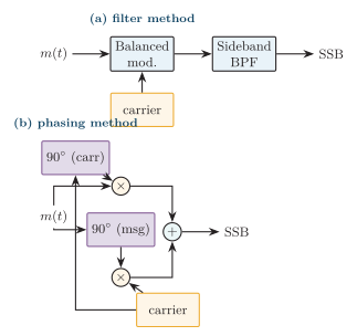
SSB generation: (a) filter method — balanced modulator followed by a sharp sideband BPF; (b) phasing method — two balanced modulators with shifts of message and carrier summed so one sideband cancels.
In the filter method, DSB-SC is generated at a convenient IF so a sharp crystal or mechanical filter can select one sideband before conversion to the final RF. The phase-shift method cancels one sideband by adding or subtracting the outputs of quadrature message/carrier paths. The Weaver method instead uses two quadrature mixing stages with low-pass filters and is convenient in DSP and IC implementations.
Detection: reinsert a carrier with a BFO/PLL and product-detect; carrier-frequency error shifts all audio components (unnatural pitch). A small transmitted pilot can assist carrier-frequency and phase synchronization. Advantages: best bandwidth/power efficiency, narrower receiver noise bandwidth, ideal for HF voice and marine/aeronautical links. Limitations: complex generation/filtering, needs an accurate frequency reference, and simple envelope detection is unavailable.
Vestigial Sideband (VSB)
Section titled “Vestigial Sideband (VSB)”VSB transmits one full sideband plus a small vestige of the other, often with a residual carrier. It suits messages that extend near DC where an abrupt SSB filter is impractical.
Classic use: analog television video — saves bandwidth versus DSB while preserving low video frequencies.
AM-Family Comparison
Section titled “AM-Family Comparison”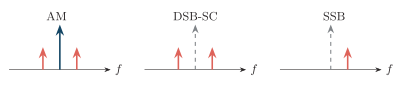
Sideband occupancy: AM keeps carrier both sidebands; DSB-SC removes the carrier (dashed) but keeps both sidebands; SSB keeps one sideband only.
| Feature | AM | DSB-SC | SSB-SC | VSB |
|---|---|---|---|---|
| Carrier | Full | Suppressed | Suppressed/pilot | Residual/full |
| Sidebands | Both | Both | One | One vestige |
| Bandwidth | ||||
| Efficiency | Low | Better | Best | Intermediate |
| Detector | Env./coherent | Coherent | Coherent/BFO | Env./coherent |
| Complexity | Lowest | Medium | Highest | Medium/high |
| Application | Broadcast | Subcarrier | HF voice | Analog TV |
Comparison of the amplitude-modulation family.
Angle Modulation
Section titled “Angle Modulation”Here the carrier amplitude is constant and information changes the instantaneous phase :
Angle modulation includes FM and PM.
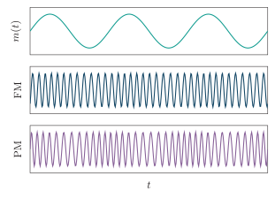
Angle-modulation waveforms: message (top), FM whose frequency deviation tracks (middle) and PM whose phase deviation tracks (bottom); both have a constant envelope.
Frequency Modulation (FM)
Section titled “Frequency Modulation (FM)”The instantaneous frequency deviation , not the total instantaneous frequency, is proportional to the message:
Single-Tone FM
Section titled “Single-Tone FM”For :
For fixed , is independent of while falls as rises.
| Type | Index | Spectrum / usage |
|---|---|---|
| NBFM | Carrier first sideband pair; | |
| WBFM | Many sideband pairs; broadcast/hi-fi |
These are descriptive regimes rather than a sharp physical boundary: NBFM means is small enough for the first-pair approximation, while increasing progressively makes more sideband pairs significant.
FM Spectrum and Carson’s Rule
Section titled “FM Spectrum and Carson’s Rule”Lines occur at ; the carrier amplitude is (which can vanish for certain ), and the th sideband pair has magnitude . There are infinitely many theoretical sidebands, but high-order terms are negligible.
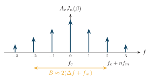
FM line spectrum: Bessel-weighted sidebands at with the significant-sideband span given by Carson’s rule.
Carson’s rule is an engineering occupied-bandwidth approximation commonly interpreted as containing roughly 98% of single-tone FM power. Exact occupied bandwidth depends on the message spectrum, deviation and chosen power criterion.
FM Generation
Section titled “FM Generation”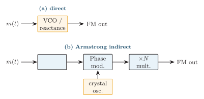
FM generation: (a) direct — message drives a VCO/reactance modulator (large deviation, less stable centre); (b) Armstrong indirect — integrate, phase-modulate a crystal carrier, then frequency-multiply (very stable).
FM Detection
Section titled “FM Detection”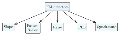
Families of FM detector, all converting frequency deviation to voltage.
-
Slope: tuned slope converts FMAM; simplest, poor linearity, needs a limiter.
-
Foster–Seeley: transformer phase discriminator; excellent linearity but requires a limiter.
-
Ratio: diode-voltage ratio gives inherent AM rejection; usually no separate limiter.
-
PLL: VCO control voltage tracks instantaneous frequency; excellent IC method.
-
Quadrature: frequency-dependent phase shift then phase detection.
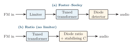
Tuned-transformer discriminators: (a) Foster–Seeley needs a preceding limiter; (b) the ratio detector has inherent amplitude rejection via a large stabilising capacitor.
A PLL provides a feedback-based alternative by converting the VCO tracking voltage into the recovered message.
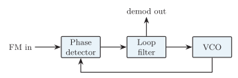
PLL FM demodulator: the loop drives the VCO to track the input frequency, so the loop-filter voltage is the recovered message.
Noise improvement. FM allows amplitude limiting and better output SNR above threshold. Because demodulated high-frequency noise rises, broadcast FM uses pre-emphasis (boost highs before Tx) and de-emphasis (complementary Rx cut). FM also shows the capture effect (stronger co-channel signal dominates) and a threshold effect (SNR collapses below a critical CNR).
Phase Modulation (PM)
Section titled “Phase Modulation (PM)”Phase deviation is proportional to the message:
For a general message, peak PM frequency deviation depends on the maximum message derivative, not merely its maximum amplitude. Applying Carson’s approximation to the single tone above gives .
FM–PM relationship: FM from a PM modulator = integrate first; PM from an FM modulator = differentiate first. Detection: phase detector, PLL or Costas loop, or an FM discriminator followed by an integrator.
Comparisons
Section titled “Comparisons”| Feature | FM | PM |
|---|---|---|
| Controlled quantity | Instantaneous frequency | Instantaneous phase |
| Phase term | ||
| Single-tone index | ||
| Fixed | independent of | |
| Generation | Integrator PM | Differentiator FM |
| Detector | Discriminator/PLL | Phase det. or discrim. integrator |
FM versus PM.
| Feature | AM | FM |
|---|---|---|
| Varied parameter | Amplitude | Frequency |
| Envelope | Carries info; varies | Ideally constant |
| Bandwidth | ||
| Noise immunity | Lower | Better above threshold |
| Tx power | Varies with ; carrier wasteful | Constant, Bessel-distributed |
| RF PA | Must preserve envelope | Efficient nonlinear PA |
| Receiver | Simple envelope detector | Limiter discriminator/PLL |
| Special effects | Overmodulation | Capture, threshold |
| Typical use | MF broadcast, aviation | VHF hi-fi, telemetry |
AM versus FM.