Adder Model Answers
Half Adder
Section titled “Half Adder”Definition and Block Diagram
Section titled “Definition and Block Diagram”-
A half adder is a combinational logic circuit that adds two single-bit binary numbers.
-
It produces two outputs: a Sum () and a Carry ().
-
It has no carry input, so it can directly add only the two least-significant bits.
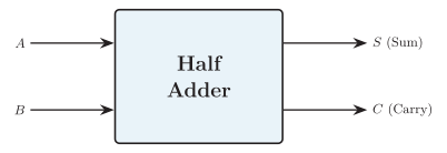
Half adder block diagram
Truth Table
Section titled “Truth Table”| 0 | 0 | 0 | |
| 0 | 1 | 1 | 0 |
| 1 | 0 | 1 | 0 |
| 1 | 1 | 0 | 1 |
For the result is , so the sum bit is and the carry bit is .
Boolean Expressions (K-Map Derivation)
Section titled “Boolean Expressions (K-Map Derivation)”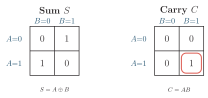
Half adder Karnaugh maps for the sum and carry outputs
The two isolated s of the sum map cannot be grouped, which gives an XOR; the single of the carry map gives an AND:
Logic Circuit Diagram
Section titled “Logic Circuit Diagram”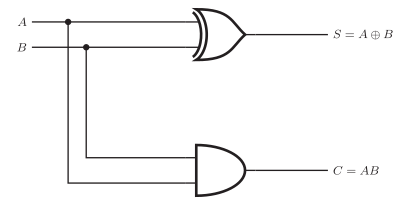
Half adder logic circuit using an XOR gate and an AND gate
-
An XOR gate driven by and produces the sum .
-
An AND gate driven by the same and produces the carry .
Limitation and Applications
Section titled “Limitation and Applications”-
Limitation: it cannot accept a carry-in () from a previous stage, so by itself it cannot add multi-bit numbers beyond the least-significant bit.
-
Applications:
-
Building block of the full adder (two half adders and an OR gate).
-
Least-significant-bit position of ripple-carry adders.
-
Arithmetic in calculators, ALUs, and address-decoding logic.
-
Full Adder
Section titled “Full Adder”Definition and Block Diagram
Section titled “Definition and Block Diagram”-
A full adder is a combinational logic circuit that adds three single-bit inputs: , , and a carry-in .
-
It produces two outputs: a Sum () and a Carry-out ().
-
Unlike the half adder, it accounts for the carry generated by a lower-order stage.
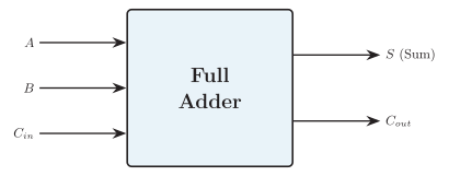
Full adder block diagram
Truth Table
Section titled “Truth Table”| 0 | 0 | 0 | 0 | |
| 0 | 0 | 1 | 1 | 0 |
| 0 | 1 | 0 | 1 | 0 |
| 0 | 1 | 1 | 0 | 1 |
| 1 | 0 | 0 | 1 | 0 |
| 1 | 0 | 1 | 0 | 1 |
| 1 | 1 | 0 | 0 | 1 |
| 1 | 1 | 1 | 1 | 1 |
K-Map Derivation and Boolean Expressions
Section titled “K-Map Derivation and Boolean Expressions”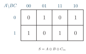
Full adder Karnaugh map for the sum output
The s form a checkerboard, so no cells can be grouped:
Carry-out ()
Section titled “Carry-out (CoutC_{out}Cout)”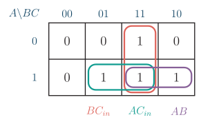
Full adder Karnaugh map for the carry-out output
The three overlapping pairs give the standard SOP form:
An implementation-friendly form using the first half adder’s XOR is:
Logic Circuit Diagrams
Section titled “Logic Circuit Diagrams”Method 1 — Basic gates (direct SOP)
Section titled “Method 1 — Basic gates (direct SOP)”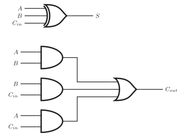
Full adder using a three-input XOR, three AND gates, and a three-input OR gate
-
A 3-input XOR on , , gives the sum .
-
Three AND gates form , , , and a 3-input OR combines them into .
Method 2 — Two half adders and an OR gate
Section titled “Method 2 — Two half adders and an OR gate”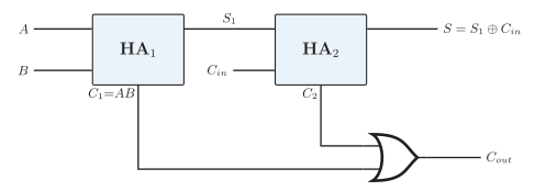
Full adder built from two half adders and an OR gate
-
HA adds and : and .
-
HA adds and : and .
-
An OR gate combines the carries: .
Applications
Section titled “Applications”-
Cascaded to form parallel adders (ripple-carry and carry-lookahead) that add multi-bit numbers in 8-, 16-, and 32-bit CPUs.
-
Core of the arithmetic logic unit (ALU) in microprocessors.
-
Used in address generation and multiplier circuits.