Network Technologies: ISDN, ATM, PDH/SDH and DSL
The Integrated Services Digital Network (ISDN) (ITU-T)ISDN (Integrated Services Digital Network) is a set of communication standards defined by the ITU-T (formerly CCITT) to allow simultaneous digital transmission of voice, video, data, and other network services over the traditional circuits of the public switched telephone network (PSTN).The foundational ITU-T recommendations for ISDN are categorized under the I-series (I.100 to I.700).
Core Principles of ISDN (ITU-T Framework)
Section titled “Core Principles of ISDN (ITU-T Framework)”-
Support for voice and non-voice applications:
-
One integrated digital network carries multiple service types over standardized access interfaces.
-
Supported applications include digital telephony, data transfer, facsimile, telemetry, image transfer, and audiovisual communication.
-
The attainable service quality and rate depend on the selected B or H bearer and the access interface.
-
-
Support for switched and non-switched applications:
-
Circuit-switched: Establishes an on-demand bearer connection for voice or data and releases it after use.
-
Packet-mode: Provides supported packet services over a D- or B-channel arrangement without treating every application as a dedicated circuit.
-
Non-switched: Provides permanent or leased digital connections without per-call establishment.
-
-
Reliance on connections:
-
The B channel is the basic bearer building block for speech or data.
-
This rate corresponds to conventional PCM speech sampled at with 8 bits per sample:
-
- D channels carry signalling and supported packet data, while H channels aggregate multiple basic time-slot equivalents for higher-rate bearers.4. Intelligence in the network and terminals:
- Network equipment performs call control, routing, supervision, maintenance, charging, and supplementary-service processing.
- ISDN terminals and terminal adapters execute signalling, protocol, and service-adaptation functions at the user side.
5. Layered protocol architecture:
- ISDN follows OSI-style layering with defined physical-, data-link-, and network-layer procedures.
- Bearer traffic and D-channel call-control signalling use distinct logical paths and protocol functions.
- Standardized functional groups, reference points, and protocols promote modular implementation and interoperability.
ISDN Channels
Section titled “ISDN Channels”-
B channel (bearer channel):
-
Rate: in each direction.
-
Role: Carries user information rather than ISDN call-control signalling.
-
Connection modes: Supports switched or permanent bearer connections.
-
Applications: Carries PCM speech, audio, or digital data.
-
Aggregation: Multiple B channels may be bonded when the service and terminal equipment support it.
-
-
D channel (signalling channel):
-
Rate: in BRI and in PRI.
-
Primary role: Carries out-of-band common-channel signalling independently of B-channel user traffic.
-
Call control: Supports call setup, progress, supervision, release, and supplementary services.
-
Packet mode: May also carry supported packet-mode user data on a separate logical link.
-
-
H channel (higher-rate bearer family):
-
H0: .
-
H10: .
-
H11: .
-
H12: .
-
Role: Provides higher-rate user-information bearers by aggregating basic time-slot equivalents.
-
Applications: Supports high-speed data, high-quality audio, video, and videoconferencing.
-
ISDN Protocol Architecture
Section titled “ISDN Protocol Architecture”-
D-channel stack: ISDN specifies complete physical-, data-link-, and network-layer procedures for signalling.
-
B/H bearer stack: B and H channels share the access physical layer, but their higher-layer protocols depend on the selected bearer service.
-
Physical layer:
-
Standards: ITU-T I.430 defines basic-rate access; I.431 defines primary-rate access.
-
Signal functions: Specifies line coding, framing, and bit timing.
-
Access functions: Controls activation, deactivation, and physical-layer maintenance.
-
Multiplexing: Places B or H bearers and the D channel onto the physical access.
-
-
Data-link layer:
-
D channel: Uses ITU-T Q.921 Link Access Procedure for the D channel (LAPD).
-
Reliability: LAPD provides framing, error detection, sequencing, acknowledgements, and retransmission on the signalling link.
-
Logical links: Service access point identifiers and terminal endpoint identifiers distinguish signalling entities sharing one D channel.
-
B/H bearers: Have no universal ISDN data-link protocol; they may be transparent or use service-selected framing such as LAPB or Frame Relay.
-
-
Network layer:
-
Call control: ITU-T Q.931 messages establish, modify, supervise, and release bearer connections over the D channel.
-
Packet services: Supported deployments may use X.25 procedures over a D- or B-channel arrangement.
-
Bearer protocols: Protocols above B and H channels depend on the selected bearer service.
-
Scope boundary: ATM belongs to broadband ISDN and is not part of the narrowband ISDN bearer stack.
-
Figure contrasts the defined D-channel signalling stack with service-dependent B/H bearer transport over their shared physical access.

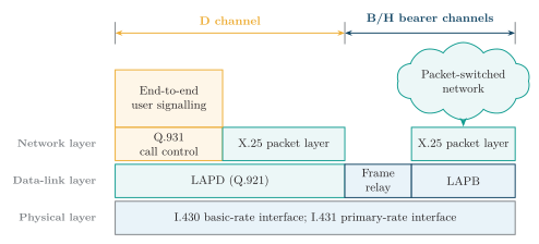
ISDN protocol architecture for D-channel signalling and B/H-channel bearer transport.
ISDN Interfaces
Section titled “ISDN Interfaces”-
Basic Rate Interface (BRI/BRA):
-
Structure: two B channels and one D channel.
-
Aggregate channel rate:
-
- Physical rate: $192\,\mathrm{kbit/s}$ at the S/T interface after framing and other physical-layer overhead.
- Deployment: residential and small-office access over suitable copper subscriber loops, with ISDN line termination and compatible customer equipment.
2. Primary Rate Interface on E1 (E1 PRI):
- Structure: 30 B channels and one $64\,\mathrm{kbit/s}$ D channel; TS0 carries framing and related overhead, while TS16 normally carries D-channel signalling.
- Aggregate bearer-plus-signalling rate:- Physical line rate: $2.048\,\mathrm{Mbit/s}$.
- Deployment: PBXs, enterprises, exchanges, and other high-channel-count installations using E1 systems.3. Primary Rate Interface on T1 (T1 PRI):
- Structure: 23 B channels and one $64\,\mathrm{kbit/s}$ D channel.
- Aggregate bearer-plus-signalling rate:- Physical line rate: $1.544\,\mathrm{Mbit/s}$, including T1 framing overhead.
- Deployment: PBXs ( PBX (Private Branch Exchange)) and enterprise access in North American T1 systems.Access Path, Reference Points and Functional Groups
Section titled “Access Path, Reference Points and Functional Groups”-
Functional groups:
-
TE1: An ISDN-compatible terminal, such as an ISDN telephone or data terminal.
-
TE2: A non-ISDN terminal that requires adaptation before connection to ISDN.
-
TA: The terminal adapter that converts the TE2 interface into an ISDN-compatible form.
-
NT1: The physical network termination for the subscriber loop.
-
NT2: Optional customer-premises switching or concentration, such as a PBX.
-
-
Reference points:
-
R: Between TE2 and its terminal adapter.
-
S: Between TE1 or a terminal adapter and NT2.
-
T: Between NT2 and NT1; S and T coincide as S/T when NT2 is absent.
-
U: Between NT1 and the exchange line termination.
-
Figure follows three representative access paths. TE1 data and telephone terminals join at S directly, whereas a TE2 first passes through a terminal adapter at R. An optional NT2 provides premises switching or concentration, NT1 terminates the subscriber loop, and the ISDN exchange connects the bearer to a switched, packet, or private-line network.

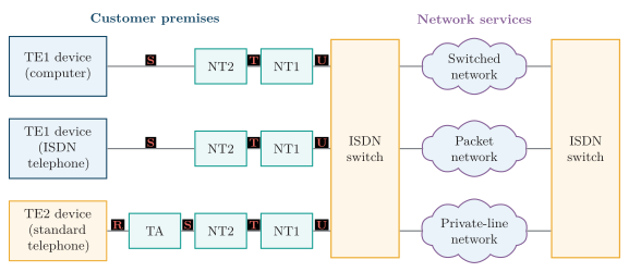
ISDN reference configuration for TE1 and TE2 terminals and network service types.
ISDN Services
Section titled “ISDN Services”-
Bearer services:
-
Provide information transport between user–network interfaces without prescribing terminal functions.
-
Support circuit- or packet-mode transfer through switched or permanent connections.
-
Carry speech/audio or unrestricted digital data.
-
Underlie applications such as electronic mail, database and Internet access, fund transfer, image exchange, and alarm reporting; these applications are not separate channel types.
-
-
Teleservices:
-
Combine bearer transport with standardized end-to-end terminal functions.
-
Include digital telephony, facsimile, teletex/videotex, and supported audiovisual communication.
-
-
Supplementary services:
-
Enhance an existing bearer service or teleservice rather than supplying transport independently.
-
Provide identification and addressing features, including calling-number identification and multiple subscriber numbers.
-
Provide call-handling features such as call diversion and call waiting.
-
Provide closed user groups and charging information.
-
Advantages and Practical Limits
Section titled “Advantages and Practical Limits”-
Digital quality and monitoring:
-
Regeneration prevents cumulative analogue noise and distortion from being amplified at every stage.
-
Direct digital transmission normally gives lower data-error rates than voiceband-modem operation on a comparable access.
-
Digital framing and maintenance functions support in-service performance monitoring.
-
-
Faster call establishment:
-
The D channel carries call-control signalling independently of active bearer traffic.
-
Digital data calls avoid analogue-modem training after bearer establishment.
-
Actual setup time still depends on the terminal, exchange, and network path.
-
-
Integrated capacity:
-
One access carries multiple bearer and signalling channels.
-
Simultaneous services can use separate channels on the same interface.
-
For example, one B channel can carry speech, another can carry data, and the D channel can handle signalling.
-
-
Standardization and supplementary control:
-
Defined interfaces and protocols support interoperable terminals and network equipment.
-
Network-based signalling supplies identification, diversion, charging, and related supplementary features.
-
Broadband ISDN (B-ISDN)
Section titled “Broadband ISDN (B-ISDN)”Purpose and Technology Foundation
Section titled “Purpose and Technology Foundation”-
Purpose: Integrate low-rate and broadband, bursty and continuous, and real-time and non-real-time services.
-
Transfer and switching: ATM supplies statistical cell multiplexing, virtual connections, traffic contracts, and QoS-aware resource control; circuit-mode services can be emulated over the same transport.
-
Transmission: Optical subscriber and trunk systems at synchronous transport rates provide the required bandwidth and low attenuation.
-
Implementation: High-speed switching, memory, codecs, cameras, and displays made ATM processing and broadband multimedia terminals practical.
B-ISDN Service Categories
Section titled “B-ISDN Service Categories”-
Interactive services – two-way exchange:
-
Conversational: Real-time voice, videotelephony, or videoconferencing.
-
Messaging: Store-and-forward multimedia mail, document transfer, or facsimile.
-
Retrieval: User-requested database, image, or video-library information.
-
-
Distribution services – provider-to-subscriber transfer:
-
Without presentation control: Continuous broadcast; the user cannot control programme start or sequence.
-
With presentation control: Individually selected or sequenced on-demand/cyclical material.
-
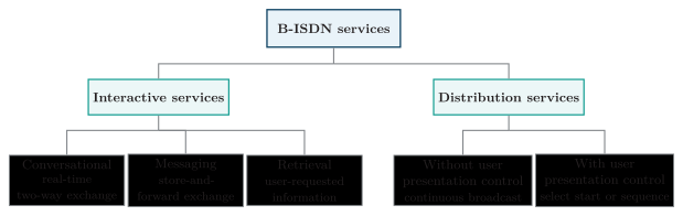
B-ISDN service taxonomy.
Historical Access Profiles
Section titled “Historical Access Profiles”Historical profiles provided symmetric STM-1, asymmetric STM-1 upstream/STM-4 downstream, or symmetric STM-4 physical access.
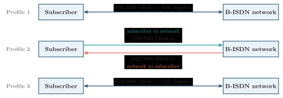
Historical B-ISDN access-rate profiles.
These are nominal line rates; protocol overhead and traffic contracts reduce application throughput.
Functional Architecture
Section titled “Functional Architecture”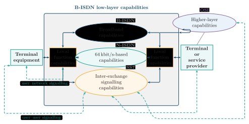
B-ISDN functional architecture with bidirectional capability and signalling relationships.
Figure shows the bidirectional capability paths between endpoint functions, local boundary functions, the low-layer network, and higher-layer service logic.

-
B-ISDN low-layer capabilities:
-
Broadband capabilities (B-ISDN): Switch and statistically multiplex voice, video, and data in fixed 53-byte ATM cells over virtual connections.
-
-based capabilities (N-ISDN): Support and interwork legacy narrowband services and bearer characteristics.
-
Inter-exchange signalling capabilities (SS7): Coordinate connection control, routing, resource allocation, supervision, and release between network exchanges.
-
-
Local function capabilities (LFCs):
-
Sit at the user-side and service-provider-side boundaries of the low-layer network.
-
Mediate between endpoint functions and the appropriate transfer, interworking, or signalling capability.
-
Adapt local access information and control requests to the functions offered by the B-ISDN network.
-
-
Signalling paths:
-
User–network signalling: Connects terminal control functions to the adjacent LFC for service requests, connection setup or modification, supervision, and release.
-
User–user signalling: Passes through the inter-exchange signalling capability and branches toward the peer terminal or service provider and its higher-layer capabilities.
-
The dashed paths denote bidirectional logical signalling relationships carried by the underlying network.
-
-
Higher-layer capabilities:
-
Reside in terminal or service-provider systems outside the low-layer transfer core.
-
Implement session control, application processing, presentation, storage, retrieval, and service logic.
-
Support services such as videoconferencing, multimedia messaging, information retrieval, and other application-specific functions.
-
Protocol Reference Model
Section titled “Protocol Reference Model”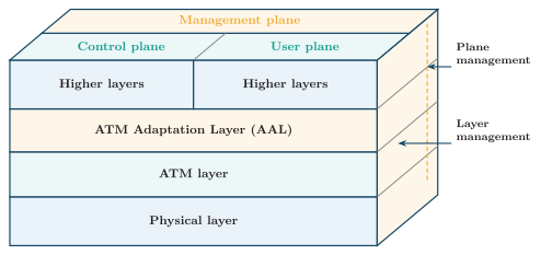
B-ISDN protocol reference model.
Figure is read along two perpendicular axes: the front face is the protocol-layer stack, while the top and right faces separate user, control, and management functions.

-
Protocol layers – front face:
-
Physical layer: Transmits cells over the medium; its physical-medium and transmission-convergence functions provide bit timing, framing, cell delineation, HEC processing, and rate adaptation.
-
ATM layer: Generates and removes cell headers, multiplexes cells, translates VPI/VCI labels, and relays cells through the network.
-
ATM Adaptation Layer (AAL): Adapts higher-layer information to 48-byte cell payloads through convergence and segmentation-and-reassembly functions.
-
Higher layers: Contain plane-specific application, service, and signalling protocols; therefore separate higher-layer blocks appear for control and user functions.
-
-
Control plane – top-left region:
-
Carries signalling rather than user payload.
-
Establishes, modifies, supervises, and releases virtual connections.
-
Uses the physical, ATM, and AAL layers beneath its own higher-layer signalling protocols.
-
-
User plane – top-right region:
-
Transfers voice, video, and data together with associated user-plane flow and error-control functions.
-
Uses the same physical, ATM, and AAL layer structure beneath service-dependent higher-layer protocols.
-
-
Management plane – rear and right faces:
-
Plane management: Coordinates the complete protocol model, including system configuration, fault coordination, resource coordination, and communication among planes; it is not confined to one protocol layer.
-
Layer management: Performs operation, administration, and maintenance for resources and protocol entities within each individual layer.
-
The right face is divided at the same heights as the front stack to show layer management acting across the physical, ATM, AAL, and higher layers.
-
N-ISDN and B-ISDN Comparison
Section titled “N-ISDN and B-ISDN Comparison”| Basis | N-ISDN | B-ISDN |
|---|---|---|
| Rate regime | channels; BRI and PRI | Above primary rate; historical and access |
| Access medium | Commonly existing copper subscriber loops | Broadband digital transport, principally optical fibre |
| Transfer method | Fixed-rate B/H bearers with separate D-channel signalling | Connection-oriented ATM cells with statistical multiplexing |
| Protocol model | Physical layer plus LAPD/Q.931 signalling; bearer protocols depend on service | Physical, ATM, AAL, and higher layers across user, control, and management planes |
| Main services | Digital voice, low-rate data, and supplementary services | Integrated voice, burst data, high-speed data, and real-time multimedia |
| Resource control | Predominantly fixed bearer allocation | Traffic contracts, admission control, scheduling, and differentiated QoS |
| Engineering trade-off | Simpler channelized access, but limited rate and flexibility | Flexible heterogeneous service, but cell/AAL overhead and greater signalling/traffic-management complexity |
| Historical outcome | Deployed as a legacy digital access service | Largely superseded by IP/MPLS and Ethernet before universal deployment |
Characteristics
Section titled “Characteristics”-
Connection-oriented:
-
A virtual connection is established or provisioned before user cells are transferred.
-
Cells belonging to one connection follow the established logical path in sequence.
-
-
Cell switched:
-
Every transfer unit is a fixed -byte cell.
-
Short, fixed cells support fast hardware switching and predictable per-cell serialization time.
-
-
Asynchronous statistical multiplexing:
-
A source inserts cells when it has traffic instead of owning a permanently recurring time slot.
-
Active virtual connections share link capacity statistically.
-
-
Integrated services and QoS:
-
One switching fabric carries voice, video, and computer data.
-
Service categories provide different rate, delay, delay-variation, and loss objectives.
-
-
Media independent:
- The physical layer maps ATM cells onto suitable electrical or optical transmission systems.
ATM Cell and Header
Section titled “ATM Cell and Header”-
Cell format:
-
One cell contains bytes: a -byte header and a -byte payload.
-
The header carries forwarding and control information; the payload carries AAL-adapted user information.
-
-
Connection identifiers:
-
VPI identifies a virtual path that can bundle several virtual channels.
-
VCI identifies one virtual channel within that path.
-
-
Control and protection:
-
PTI identifies payload/control status; CLP marks lower-priority cells; HEC protects the header and assists cell delineation.
-
GFC appears only at the user–network interface and is commonly unused.
-
HEC does not protect the payload; required payload recovery belongs to the AAL or higher protocols.
-
Figure shows how the same 40 header bits are allocated at the two interfaces.

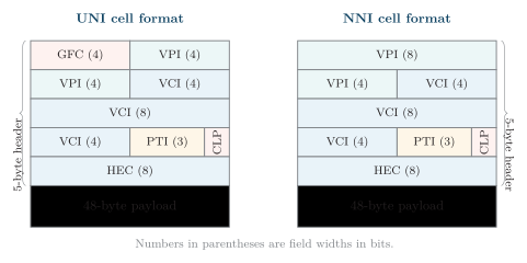
ATM UNI and NNI cell formats.
Virtual Paths, Virtual Channels and Switching
Section titled “Virtual Paths, Virtual Channels and Switching”-
Virtual channel connection (VCC):
-
Carries one logical stream of cells between endpoints.
-
Uses a VCI within a selected virtual path.
-
-
Virtual path connection (VPC):
-
Bundles VCCs that share a route.
-
Uses a VPI so the network can handle the bundle at path level.
-
-
Connection and transfer:
-
A VCC or VPC is provisioned or established by signalling before user transfer.
-
Cells carry compact VPI/VCI labels rather than a complete destination address.
-
Cells of one connection follow its logical path and retain sequence.
-
Figure shows a transmission path containing VPCs and their constituent VCCs.

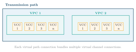
ATM transmission-path, VPC, and VCC hierarchy.
ATM Protocol Layers
Section titled “ATM Protocol Layers”The complete plane arrangement appears in Figure; the exam-level transfer stack is:
-
Physical layer:
-
Maps ATM cells onto the transmission medium.
-
Handles bit timing, transmission framing, cell delineation, and HEC processing.
-
-
ATM layer:
-
Adds or removes cell headers and multiplexes or demultiplexes cells.
-
Uses VPI/VCI labels to switch and relay cells along virtual connections.
-
-
ATM Adaptation Layer (AAL):
-
Adapts higher-layer information, segments it into 48-byte payloads, and reassembles it at the receiver.
-
AAL1 supports constant-rate timing-sensitive traffic, AAL2 low-rate real-time traffic, and AAL5 data.
-
Service Categories and Basic QoS
Section titled “Service Categories and Basic QoS”| Category | Service idea | Typical use |
|---|---|---|
| CBR | Fixed cell rate with tight timing objectives | Voice and leased-circuit emulation |
| VBR | Variable rate with real-time or non-real-time QoS objectives | Compressed audio/video and managed bursty traffic |
| ABR | Available rate adapts to network feedback | Elastic data transfer |
| UBR | Best effort with no specified rate or delay guarantee | Non-critical data |
-
QoS idea: A connection declares service needs such as rate, delay, delay variation, and cell-loss objectives.
-
Resource control: The network uses the service category and traffic contract when deciding whether and how to support the connection.
-
Qualification: Fixed cell size helps scheduling, but queueing and network load still affect end-to-end delay and loss.
Advantages, Limitations and Applications
Section titled “Advantages, Limitations and Applications”-
Advantages:
-
Integrates voice, video, and data in one switching system.
-
Statistical multiplexing shares capacity efficiently among active connections.
-
Service categories and QoS objectives support different timing and loss needs.
-
Fixed cells and compact VPI/VCI labels support fast hardware switching.
-
-
Limitations:
-
The 5-byte header consumes of cell bandwidth before AAL framing or padding overhead.
-
Segmentation and reassembly add processing, and one lost cell can damage a larger higher-layer unit.
-
Connection setup, switch state, adaptation, and traffic management increase operational complexity.
-
-
Applications and legacy:
-
Used in B-ISDN, carrier and enterprise backbones, circuit emulation, and early DSL aggregation.
-
IP/MPLS and carrier Ethernet later displaced most ATM deployments because they were operationally simpler.
-
ISDN, Frame Relay and ATM Comparison
Section titled “ISDN, Frame Relay and ATM Comparison”| Basis | ISDN | Frame Relay | ATM |
|---|---|---|---|
| Primary role | Integrated digital subscriber access | Shared packet-data WAN service | Broadband cell transport and switching |
| Transfer unit | B/H bearer time slots and D-channel signalling frames | Variable-length frames | Fixed 53-byte cells |
| Connection model | Switched or permanent bearers, with optional packet service | Connection-oriented PVCs or SVCs | Connection-oriented VPCs and VCCs |
| Traffic handling | Fixed-rate channel allocation | Statistical multiplexing with CIR and congestion indicators | Statistical multiplexing with service categories, traffic contracts, and QoS control |
| Typical historical use | Digital voice and data access | Branch-office WANs | B-ISDN, carrier backbones, broadband aggregation, and circuit emulation |
The Plesiochronous Digital Hierarchy (PDH) multiplexes tributaries whose clocks are nominally equal but not phase/frequency locked, using bit stuffing (justification) to absorb the small clock differences.
-
Justification: The multiplexer inserts non-information bits when a tributary cannot supply a bit at a scheduled opportunity. Control information identifies these positions so the demultiplexer removes stuffing and recovers the tributary timing.
-
Limitations: Extracting a low-rate tributary usually requires successive demultiplexing stages. Limited management overhead and different European, North American, and Japanese rate hierarchies complicate interconnection and maintenance.
| Level | Bit rate | Approx. voice ch. |
|---|---|---|
| E1 | 2.048 Mbit/s | 30 |
| E2 | 8.448 Mbit/s | 120 |
| E3 | 34.368 Mbit/s | 480 |
| E4 | 139.264 Mbit/s | 1920 |
| T1/DS1 | 1.544 Mbit/s | 24 |
| T2/DS2 | 6.312 Mbit/s | 96 |
| T3/DS3 | 44.736 Mbit/s | 672 |
The Synchronous Digital Hierarchy (SDH) is a standardised optical transmission hierarchy using synchronised network clocks and a structured frame with pointers and rich overhead, allowing efficient add/drop and strong management.
An STM-1 frame contains bytes and repeats every , giving . Tributaries are mapped into virtual containers; pointers locate their payloads and accommodate limited phase and frequency offsets relative to the transport frame.
| Level | Bit rate |
|---|---|
| STM-1 | 155.52 Mbit/s |
| STM-4 | 622.08 Mbit/s |
| STM-16 | 2.48832 Gbit/s |
| STM-64 | 9.95328 Gbit/s |
| STM-256 | 39.81312 Gbit/s |
-
Terminal multiplexer: Maps lower-rate tributaries into containers and assembles the STM signal at the end of a transport path.
-
ADM (add/drop multiplexer): Accesses selected tributary containers while forwarding the remaining traffic, without the cascade of PDH demultiplexers.
-
DXC (digital cross-connect): Connects selected digital paths between ports, allowing traffic to be rearranged without manual patching.
-
Regenerator: Recovers timing and reconstructs degraded digital signals between transport nodes.
-
Protection: Provisioned redundant paths and protection signalling reroute affected traffic after a failure. Ring topology alone is insufficient without spare capacity and a configured protection scheme.
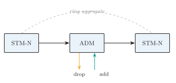
SDH ring with an add-drop multiplexer.
PDH and SDH Comparison
Section titled “PDH and SDH Comparison”| Basis | PDH | SDH |
|---|---|---|
| Synchronization | Tributary clocks are nominally equal but independent; bit stuffing absorbs small rate differences | Network elements trace synchronized references; pointers accommodate payload phase and frequency offsets |
| Multiplexing | Bit-interleaved stages use justification bits and control information | Byte-interleaved STM frames carry tributaries mapped into virtual containers |
| Frame and payload organization | Framing is rate- and region-specific; justification makes lower-rate payload positions less directly accessible | An STM-1 frame contains bytes every ; overhead, pointers, and virtual containers give payloads a structured location |
| Tributary access | A low-rate tributary normally requires successive demultiplexing through intermediate hierarchy levels | An ADM can access selected virtual containers while forwarding the remaining traffic |
| Hierarchy and interworking | European, North American, and Japanese hierarchies use different rates and mappings | Standardized STM-N rates and interfaces simplify multivendor and international interconnection |
| Operations and maintenance | Limited overhead provides relatively modest alarm, monitoring, and management capability | Rich section and path overhead supports alarms, performance monitoring, synchronization, and management |
| Cross-connection | Rearranging tributaries is equipment-intensive because intermediate levels must be exposed | A DXC can switch selected digital paths between ports at defined container levels |
| Protection | Protection is comparatively limited and implementation-dependent | Standardized protection switching can use provisioned spare paths or ring capacity |
| Representative rates and scaling | E-carrier: to ; T-carrier: to , with additional hierarchy stages for growth | STM-1/4/16/64 provide , , , and |
| Typical role and status | Legacy access, leased-line, and lower-rate trunk transport; largely retained for compatibility with installed circuits | Metro and core transport, optical rings, and aggregation of PDH tributaries; still deployed but increasingly complemented or replaced by OTN and packet transport |
DSL Technologies
Section titled “DSL Technologies”Digital Subscriber Line (DSL) is a family of digital transmission technologies for copper subscriber pairs. Voice-sharing variants such as ADSL use spectrum above the POTS band and separate voice and data with filters; not every DSL variant supports simultaneous analog telephony.
Operating Principle
Section titled “Operating Principle”-
Spectrum above voice: A copper pair can carry frequencies well above the – POTS voice band. A voice-sharing DSL system places data in higher-frequency bands.
-
Frequency separation: Splitters or microfilters keep low-frequency telephone signals out of the DSL receiver and high-frequency DSL energy out of the telephone.
-
Full-duplex data: Separate upstream and downstream bands, echo cancellation, or both permit simultaneous two-way data transmission, depending on the DSL standard and band plan.
-
Always-on link: The modem trains with the DSLAM, selects a stable rate and modulation parameters, and normally remains synchronized without placing a dial-up telephone call.
-
Shared beyond the loop: The copper pair is dedicated between one subscriber and the serving DSLAM, but DSLAM uplinks and the provider backbone are shared resources.
Network Architecture and Components
Section titled “Network Architecture and Components”-
Copper subscriber loop: One twisted pair connects the customer premises to a central office or remote cabinet. Loop length, wire gauge, joints, and crosstalk determine usable DSL spectrum.
-
Customer splitter or microfilters: Separate the POTS voice branch from the DSL branch in installations that share the pair with analogue telephony.
-
DSL modem or gateway: Modulates digital user traffic onto the copper pair, demodulates received symbols, performs line training, and commonly includes routing or bridging functions.
-
DSLAM: Terminates many subscriber DSL links, concentrates their data traffic, and forwards it to the provider’s aggregation or IP network.
-
Central-office splitter and voice switch: In POTS-sharing systems, the low-frequency branch continues toward the PSTN while the high-frequency branch terminates on the DSLAM. Modern access nodes may integrate these functions.
Figure shows the complete voice and data paths.


End-to-end DSL access topology with POTS coexistence.
Stepwise Operation
Section titled “Stepwise Operation”-
The modem and DSLAM train, measure the line, and negotiate a stable profile and synchronization rate.
-
Customer data is modulated onto high-frequency carriers; the voice signal remains in the baseband POTS range.
-
The splitter combines or separates the two spectral regions without converting voice into DSL data.
-
The copper loop carries voice and DSL simultaneously to the serving access node.
-
The network-side splitter directs voice toward the PSTN and DSL data toward the DSLAM and provider backhaul.
ADSL Spectrum and DMT
Section titled “ADSL Spectrum and DMT”An illustrative non-overlapping ADSL Annex A plan over POTS uses:
-
Voice: approximately –.
-
Guard region: approximately –.
-
Upstream data: approximately –.
-
Downstream data: approximately –.
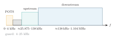
ADSL Annex A frequency allocation.
-
Discrete multitone (DMT): Divides the data spectrum into narrow subcarriers spaced apart. Full-rate ADSL uses up to 256 tone positions across approximately ; ADSL2+ doubles the upper spectrum to approximately .
-
Training and bit loading: The modem measures SNR on each tone and assigns more bits to clean tones, fewer bits to noisy tones, and none to unusable tones. The sum of all allocations determines the synchronization rate.
-
Rate adaptation: Bitswap and supported rate-adaptation methods redistribute loading as line conditions change. “RADSL” commonly describes this adaptive behavior rather than one universal, separate physical-layer standard.
-
Error protection: Forward-error correction improves resilience; interleaving spreads burst errors but adds latency. Fast-path operation reduces latency at the cost of lower burst-noise tolerance.
xDSL Technologies
Section titled “xDSL Technologies”-
ADSL, ADSL2, and ADSL2+:
-
Allocate more capacity downstream than upstream and are suited to download-heavy residential access while sharing the pair with POTS in suitable annexes.
-
G.992.1 ADSL has nominal maxima near downstream and upstream. G.992.5 ADSL2+ extends spectrum to and nominal downstream capacity to about ; upstream depends on annex and may reach about with Annex M.
-
-
ADSL Lite (G.lite):
-
G.992.2 is a reduced-rate ADSL profile designed for easier, nominally splitterless customer installation.
-
Its historical maxima are approximately downstream and upstream; it uses fewer DMT tones than full-rate ADSL.
-
-
HDSL:
-
G.991.1 provides symmetric or service as a repeaterless T1/E1 replacement over multiple copper pairs, commonly two or three depending on system and line rate.
-
Historical implementations used line codes such as 2B1Q or CAP and normally required dedicated pairs rather than POTS coexistence.
-
-
SDSL and SHDSL:
-
SDSL is a generic name for proprietary single-pair symmetric DSL, commonly used for business data and usually without POTS sharing.
-
SHDSL, standardized by G.991.2, is the interoperable symmetric successor and supports profile-dependent rates over one or more bonded pairs.
-
-
VDSL and VDSL2:
-
Use much wider spectrum over short copper loops, commonly as the final segment of fibre-to-the-cabinet or fibre-to-the-building systems.
-
First-generation VDSL supports profile-dependent rates up to roughly downstream and upstream. VDSL2 profiles can exceed on short, good-quality loops; vectoring and bonding can raise practical capacity further.
-
Typical applications include high-speed Internet, IPTV, and voice in “triple-play” access networks.
-
Rate–Reach Trade-off
Section titled “Rate–Reach Trade-off”-
ADSL reach: Service may extend toward on favorable loops at reduced rates, while substantially higher rates normally require shorter loops. This is an engineering estimate, not an absolute cutoff.
-
HDSL/SDSL reach: Legacy symmetric systems commonly operate over several kilometres; pair count, line code, gauge, and target rate determine the actual limit.
-
VDSL reach: Peak VDSL/VDSL2 rates require loops of a few hundred metres. Performance falls rapidly with distance; at longer reach, VDSL2 approaches ADSL-class rates.
Advantages
Section titled “Advantages”-
Reuse of installed copper: Provides broadband without replacing every subscriber loop, reducing initial civil-work cost.
-
Simultaneous voice and data: Voice-sharing variants separate POTS and DSL spectra so a call and Internet session can operate together.
-
Always-on access: The trained DSL link remains synchronized and avoids dial-up call establishment and voiceband-modem negotiation.
-
Dedicated local loop: Each subscriber has a dedicated copper pair to the DSLAM, although DSLAM uplinks and the wider provider network remain shared.
-
Flexible deployment: Asymmetric, symmetric, long-reach, and short-reach profiles allow operators to trade rate, reach, pair count, and service mix.
Limitations
Section titled “Limitations”-
Distance dependence: Attenuation increases with frequency and loop length, so attainable rate decreases as the customer moves farther from the DSLAM.
-
Copper quality: Aging cable, water ingress, poor joints, bridge taps, and varying wire gauge can reduce stability and throughput.
-
Crosstalk and interference: Signals in neighboring pairs and external radio or electrical noise reduce usable tone capacity.
-
Service restrictions: Not every DSL variant shares a pair with POTS, and availability depends on operator equipment, loop qualification, and supported profiles.
-
Lower future capacity than fibre: Copper supports less bandwidth and shorter high-rate reach than optical access, so fibre has progressively replaced DSL.
DSL was a major transition from voiceband dial-up to always-on broadband because it reused the installed local loop. Its central engineering lesson is the trade-off among spectrum, rate, reach, and copper-loop quality.
Numbering, Routing and Charging Plans
Section titled “Numbering, Routing and Charging Plans”A numbering plan defines how telephone numbers are structured and assigned so that calls can be uniquely addressed and routed.
-
E.164: A geographic international number comprises a country code and national significant number, commonly split into national destination code and subscriber number. The maximum is 15 digits. The displayed “” and dialling prefixes such as an international access code are not part of those digits.
-
Allocation and growth: The plan must avoid ambiguous assignments, leave capacity for expansion, and support appropriate national emergency and service codes. Short national service codes are not necessarily complete E.164 international numbers.
-
Portability: A number may remain unchanged when the subscriber changes provider. Routing can therefore require a portability-database lookup rather than relying only on the original prefix allocation.
Routing Types
Section titled “Routing Types”| Type | Description |
|---|---|
| Fixed | Same route always used for a destination |
| Alternate | Overflow to alternate route if main busy |
| Dynamic | Route changes with traffic/load/failure |
| Hierarchical | Through local, tandem, transit levels |
| Non-hierarchical | More direct exchange-to-exchange |
-
Routing policy: After analysing the destination and any portability information, the exchange selects an eligible outgoing route and circuit. Alternate routes reduce blocking or preserve service during failures, subject to cost, capacity, and operator policy.
-
Charging: Tariff rules convert recorded usage into charges. They may depend on duration, destination, volume, service class, roaming, or time of day. Flat-rate and usage-based tariffs describe pricing; prepaid and postpaid describe when payment or credit is settled.
-
Call detail record (CDR): Records calling and called identities, setup/answer/release times, duration, selected trunk or route, and charge class. Mediation and rating systems validate the records and apply the tariff.