Analog Receivers
Receiver Purpose and Classification
Section titled “Receiver Purpose and Classification”A radio receiver selects a desired modulated signal from the many signals at its antenna, amplifies it, demodulates it and reproduces the original information with acceptable strength and fidelity.
Its essential tasks are selection of the wanted carrier, low-noise amplification of a weak signal, frequency conversion to a fixed IF, demodulation to recover baseband, audio/data amplification, and automatic control of gain or tuning.
| Receiver | Principle | Main merit | Main limitation |
|---|---|---|---|
| Crystal | Tuned circuit + diode, no gain | Simplest, no supply | Very low sensitivity/selectivity |
| TRF | Amplifies selected signal at RF | Simple signal path | Tracking, nonuniform bandwidth |
| Superheterodyne | Converts every RF to one fixed IF | High uniform gain/selectivity | Mixer, LO, image response |
| Direct-conversion | Mixes RF to zero IF (baseband) | Highly integrable | DC offset, noise, LO leakage |
Main receiver types; for AM/FM broadcast the superheterodyne is standard.
Tuned Radio-Frequency (TRF) Receiver
Section titled “Tuned Radio-Frequency (TRF) Receiver”In a TRF receiver the selected station is amplified at its original radio frequency; there is no mixer, local oscillator or IF stage.
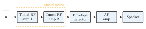
TRF receiver: antenna cascaded tuned RF amplifiers envelope detector AF amplifier speaker; all resonators track together.
Working
Section titled “Working”The antenna receives many stations; each RF stage has a parallel resonant circuit tuned to the wanted carrier, all varied together by a ganged capacitor. Cascaded stages give gain and out-of-band rejection, an envelope detector recovers the AM message, and the AF amplifier drives the speaker.
Because is roughly constant, the absolute bandwidth grows with tuning frequency — so selectivity is not uniform across the band.
Advantages and Limitations
Section titled “Advantages and Limitations”Superheterodyne Receiver
Section titled “Superheterodyne Receiver”A superheterodyne receiver translates every selected RF carrier to a fixed intermediate frequency (IF), where most gain and channel selectivity are obtained.
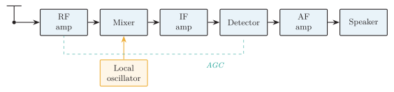
Superheterodyne receiver: antenna RF amp mixer (fed by the local oscillator) fixed-IF amp detector AF amp speaker, with AGC feedback to the RF/IF stages.
| Block | Function |
|---|---|
| Antenna / input network | Capture RF energy; provide initial band selection and impedance matching |
| RF amp / preselector | Select band, improve sensitivity, reject the image before mixing |
| Local oscillator (LO) | Tunable sinusoid tracking receiver tuning |
| Mixer | Multiply RF and LO to give sum and difference frequencies |
| IF filter/amplifier | Most gain and adjacent-channel selectivity at one fixed frequency |
| Detector | Recover the AM or FM message |
| AGC | Vary RF/IF gain so output stays usable over a wide input range |
| AF amplifier | Voltage and power gain for the loudspeaker |
Superheterodyne block functions.
Frequency Conversion
Section titled “Frequency Conversion”The mixer produces and ; the IF filter keeps the difference.
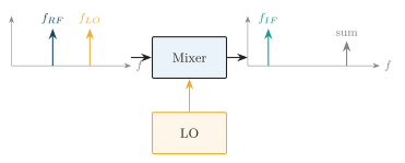
Mixer frequency conversion: and in; the IF filter selects the difference and discards the sum.
Common broadcast IFs are (AM) and (FM). A fixed IF gives steep repeatable filters, stable high gain, and one detector frequency; only the RF preselector and LO must track.
Image Frequency
Section titled “Image Frequency”An image frequency is an undesired RF that produces the same IF as the wanted signal for a given LO. After mixing the IF filter cannot separate it, so it must be rejected by the RF preselector.
Image response is reduced by a tuned RF preselector, a higher first IF (image sits farther away), multiple tuned RF circuits, or a dual-conversion plan (high first IF for image rejection, low second IF for sharp selectivity). Hence the design trade-off: high IF better image rejection, but low IF easier narrow channel filtering.
Receiver Performance Terms
Section titled “Receiver Performance Terms”| Term | Meaning | Measure / consequence |
|---|---|---|
| Sensitivity | Usable output from a weak input | Min. usable RF input for a specified SNR |
| Selectivity | Accept wanted channel, reject nearby | IF bandwidth, shape factor, ACR |
| Fidelity | Reproduce message without distortion | Flat message-band response, low distortion |
| Signal-to-noise ratio | Recovered signal vs. noise power | Higher SNR clearer reception |
| Image rejection | Suppress the image input | Set by RF preselection and IF plan |
| Stability | Stay tuned without drift/oscillation | Depends on LO, AGC, circuit design |
Receiver performance terms.
Narrowing the IF filter improves adjacent-channel selectivity, but a filter narrower than the modulation bandwidth cuts wanted sidebands and lowers fidelity.
AM Receiver
Section titled “AM Receiver”A practical AM broadcast receiver uses the superheterodyne chain above. The RF amp selects the station, the mixer converts to , the IF filter passes carrier plus both sidebands, a diode envelope detector recovers the message (and a DC control component), and the AF stages drive the speaker. For maximum audio :
Automatic Gain Control (AGC)
Section titled “Automatic Gain Control (AGC)”AGC derives a slowly varying DC from the detected signal and uses it to lower RF/IF gain on strong stations and raise it on weak ones, giving nearly constant output, overload prevention and wider dynamic range. Its time constant is slow relative to the audio, so it follows average carrier level rather than removing modulation. AM limitations: amplitude noise is detected with the envelope; ACR depends heavily on IF filtering; a simple envelope detector cannot demodulate DSB-SC/SSB; fading changes recovered amplitude unless AGC compensates.
FM Receiver
Section titled “FM Receiver”An FM receiver also uses superheterodyne conversion, but its post-IF stages differ because information is carried by instantaneous frequency.
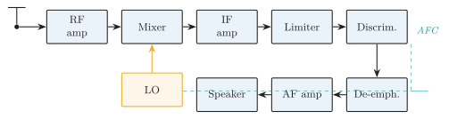
Superheterodyne FM receiver: RF amp mixer/LO IF amp limiter discriminator de-emphasis AF amp speaker; a slow discriminator error feeds AFC back to the LO.
Limiter, Discriminator and De-emphasis
Section titled “Limiter, Discriminator and De-emphasis”The limiter clips amplitude changes from noise/fading while keeping zero crossings, since ideal FM has constant envelope; it is essential before amplitude-sensitive slope and Foster–Seeley detectors (ratio and PLL detectors are less AM-sensitive). The discriminator converts frequency deviation to voltage with a linear S-curve: at , positive on one side, negative on the other, and in the linear range.
Because FM noise power rises toward the top of the audio band, the transmitter applies pre-emphasis and the receiver a complementary first-order RC de-emphasis:
Automatic Frequency Control (AFC)
Section titled “Automatic Frequency Control (AFC)”AFC uses a slowly varying component of the discriminator output to correct LO drift: if the IF center moves, the discriminator’s DC error (whose polarity shows tuning direction) drives a varactor/controlled oscillator back to correct tuning. AGC controls gain; AFC controls frequency — do not confuse them. FM merits: amplitude-noise rejection after limiting, capture effect, high fidelity above threshold, constant-envelope RF. Limitations: wider bandwidth, more complex circuitry, rapid SNR collapse below threshold, and need for accurate alignment.
AM vs. FM Receiver Comparison
Section titled “AM vs. FM Receiver Comparison”| Feature | AM superhet | FM superhet |
|---|---|---|
| Common IF | ||
| Information parameter | Carrier amplitude | Instantaneous frequency |
| Before detector | IF amplifier | IF amplifier limiter |
| Detector | Envelope / synchronous | Discriminator, ratio, quadrature, PLL |
| Post-detector | Audio coupling/filter | De-emphasis network |
| Automatic control | AGC important | AFC common; limiting reduces AGC need |
| Noise immunity | Lower (amplitude noise detected) | Better above threshold |
| Bandwidth | Narrower | Wider |
| Complexity | Lower | Higher |
AM versus FM superheterodyne receivers.