Counters
A counter is a sequential circuit that advances through a prescribed state sequence on clock events. The number of distinct states before the sequence repeats is its modulus. A mod- counter requires at least
flip-flops.
| Type | Defining feature |
|---|---|
| Asynchronous or ripple | Only the first stage receives the external clock |
| Synchronous | Every stage receives one common clock |
| Up | State increases by one modulo |
| Down | State decreases by one modulo |
| Up/down | Direction input selects increasing or decreasing sequence |
| Mod- | Repeats after exactly valid states |
| Decade | Mod-10; normally represents decimal digits 0–9 |
Counter classifications.
Asynchronous or Ripple Counters
Section titled “Asynchronous or Ripple Counters”In a ripple counter the external clock drives only the least-significant stage. Each later stage is clocked by an earlier output, so transitions do not occur simultaneously.
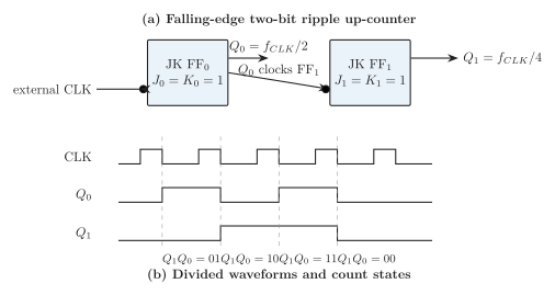
Two-bit asynchronous counter; clock bubbles specify falling-edge triggering.
For falling-edge T flip-flops with (or JK with ), connecting to the next clock gives the up-count sequence
Using instead gives the opposite direction for the same edge polarity. With positive-edge devices the required terminal reverses; verify the sequence rather than memorizing one connection.
Each stage divides frequency by two:
The simple hardware is useful for low-speed counting and frequency division, but delay accumulates. A conservative estimate is
During transitions such as , temporary intermediate codes can make an attached decoder glitch.
Synchronous Binary Counters
Section titled “Synchronous Binary Counters”Every flip-flop receives the same clock. Combinational logic decides which bits toggle before the active edge.
Synchronous up counter
Section titled “Synchronous up counter”For T flip-flops,
Bit toggles when every lower bit is 1, the carry condition. For three bits,
Synchronous down counter
Section titled “Synchronous down counter”A down-count bit toggles when all lower bits are 0, the borrow condition:
For three bits the sequence is
Synchronous up/down counter
Section titled “Synchronous up/down counter”Let select up and select down. Then
The direction input must meet setup and hold requirements like any other synchronous control.
| Property | Ripple | Synchronous |
|---|---|---|
| Clock | External clock only at first stage | Common clock at every stage |
| State change | Propagates stage by stage | All stages sample together |
| Delay | Approximately cumulative | Input logic plus one clock-to- path |
| Transient codes | Common | Reduced, though decode hazards remain |
| Hardware | Minimal | Requires excitation logic |
| Best use | Divider or low-speed counter | High-speed and arbitrary counters |
Ripple and synchronous counters compared.
Mod- and Decade Counters
Section titled “Mod-NNN and Decade Counters”If , the unused states must be removed or redirected. A simple ripple implementation detects state and drives asynchronous clear.
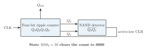
Asynchronously truncated mod-10 (decade) counter.
The decade circuit counts 0000 through 1001. Arrival at makes , so the NAND output clears all stages. The decoded state is brief; reset pulse width and decoder hazards must satisfy the flip-flop data sheet.
A synchronous mod- counter instead makes the last legal state advance directly to zero. This avoids a ripple-clear state but requires next-state logic.
Systematic Synchronous-Counter Design
Section titled “Systematic Synchronous-Counter Design”-
Write the required sequence and choose state bits.
-
Form the present-state/next-state table and state a recovery policy for unused codes.
-
Use the selected flip-flop excitation table to obtain every input.
-
Simplify each input by Boolean algebra or Karnaugh map.
-
Draw one common clock and verify every legal and unused state.
Synchronous mod-5 example
Section titled “Synchronous mod-5 example”For
one JK realization is
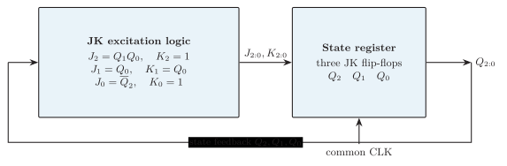
Common-clock realization of the minimized synchronous mod-5 counter.
Using gives
It also recovers from unused states: , , and .