Digital Modulation
Digital Modulation Fundamentals
Section titled “Digital Modulation Fundamentals”Digital modulation maps groups of bits to a finite set of carrier waveforms called symbols. A sinusoidal carrier may vary in amplitude, frequency, phase, or in both amplitude and phase.
| Scheme | Parameter carrying information |
|---|---|
| ASK | Amplitude |
| FSK | Frequency |
| PSK | Phase |
| QAM | In-phase and quadrature amplitudes (amplitude and phase) |
Baseband and Passband
Section titled “Baseband and Passband”Baseband transmission sends a line-coded pulse waveform in its original low-pass range, with energy near DC (Ethernet over copper, digital buses). Passband transmission maps data onto a carrier centred at nonzero (radio, satellite, modem, microwave). Passband operation permits radiation by practical antennas, channel allocation, frequency translation, and use of bandpass channels that cannot pass DC.
Bit and Symbol Quantities
Section titled “Bit and Symbol Quantities”| Quantity | Meaning |
|---|---|
| Bit rate (bit/s) | |
| Bit duration | |
| Symbol rate (Bd) | |
| Symbol duration | |
| Number of possible symbols | |
| Bits carried by each symbol |
Increasing lowers the symbol rate for a fixed bit rate, but constellation points crowd together at fixed average power and demand higher SNR.
Energy and BER
Section titled “Energy and BER”The normalised ratio allows fair power-efficiency comparison across different bit rates and bandwidths. The bit error rate (BER) is the long-run probability of a wrongly decided bit under stated channel and detection assumptions.
Binary Digital Modulation
Section titled “Binary Digital Modulation”Binary carrier modulation assigns one of two waveforms during each bit interval . The three basic schemes vary amplitude, frequency, or phase of a common carrier driven by the same data sequence.
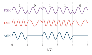
ASK, FSK and PSK carrier waveforms for the common data sequence : ASK gates the carrier on/off, FSK switches between two frequencies, and PSK flips the phase by on a bit.
The corresponding modem architecture shows how mapping, carrier multiplication, coherent recovery, and decision are implemented.
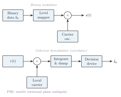
Binary modulator (data mapper multiply by carrier) and coherent demodulator (multiply by local carrier integrate-and-dump decision). Coherent PSK also requires carrier synchronization and phase-ambiguity resolution before bit assignment.
| Detection | Reference | Benefit | Cost |
|---|---|---|---|
| Coherent | Synchronised local carrier | Best BER | Carrier recovery / ambiguity handling |
| Noncoherent | No absolute phase | Simpler | Poorer BER / more BW |
Carrier recovery for PSK can lock with a rotational ambiguity (for example, in BPSK or one of rotations in -PSK). A known preamble/pilot, differential coding, or an appropriate ambiguity-resolution rule is therefore needed before assigning recovered symbols to bits. Matched filters/correlators maximise output SNR for known waveforms in additive white Gaussian noise (AWGN); the receiver samples at symbol instants and picks the most likely symbol.
Amplitude Shift Keying (ASK)
Section titled “Amplitude Shift Keying (ASK)”In binary ASK the carrier amplitude takes one of two values. The common on-off keying (OOK) case is
Generation: multiply unipolar NRZ data by the carrier (product modulator) or switch the carrier on/off. Detection: coherent (multiply by synchronised carrier, integrate, threshold) or noncoherent (envelope/square-law detector plus threshold).
With raised-cosine pulse shaping, binary ASK can instead occupy approximately under the corresponding passband/Nyquist bandwidth convention. A bandwidth answer must state both the pulse shape and the definition used; it must not compare this value directly with a rectangular-pulse null-to-null value. ASK is the simplest scheme but is sensitive to amplitude noise and fading and has a non-constant envelope (linear amplification preferred). Uses: optical intensity links, RFID, remote controls and simple telemetry.
Binary Frequency Shift Keying (BFSK)
Section titled “Binary Frequency Shift Keying (BFSK)”BFSK uses two frequencies, the mark and space :
Orthogonality and Bandwidth
Section titled “Orthogonality and Bandwidth”For coherent observation over a common minimum separation is ; simple noncoherent orthogonality often uses . A Carson-like null-to-null estimate for rectangular symbols is
Generation, Detection and Performance
Section titled “Generation, Detection and Performance”Generate by switching two oscillators, driving a VCO, or using a phase accumulator (continuous phase). Detect coherently with two correlators (choose larger output) or noncoherently with two bandpass filters and envelope detectors. A PLL that follows the two tone states or a frequency discriminator followed by thresholding provides another practical BFSK detector.
BFSK has a constant envelope (efficient nonlinear PAs) and better amplitude-noise tolerance than ASK, but usually wider bandwidth than PSK. Uses: low-speed modems, paging, caller ID, telemetry, low-power radio.
Binary Phase Shift Keying (BPSK)
Section titled “Binary Phase Shift Keying (BPSK)”BPSK uses two antipodal phases separated by :
Map bits to polar levels and drive a balanced product modulator, .
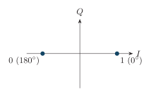
BPSK constellation: two antipodal points at and on the in-phase axis (), giving maximum Euclidean distance for a fixed bit energy.
Coherent detection recovers the carrier (Costas loop), correlates over , and decides from the sign of the sample:
DPSK encodes information in the phase change between symbols, avoiding an absolute phase reference at the cost of error propagation and slightly worse BER.
Quadrature Phase Shift Keying (QPSK)
Section titled “Quadrature Phase Shift Keying (QPSK)”QPSK uses four phase states and carries two bits/symbol:
Serial bits are grouped into dibits mapped to :
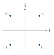
Gray-coded QPSK constellation at , , , : adjacent points differ by one bit, so a nearest-neighbour symbol error usually causes only one bit error.
| Dibit | Phase | |||
|---|---|---|---|---|
| 01 | ||||
| 11 | ||||
| 10 |
QPSK Gray mapping (one common convention).
Under ideal coherent detection and Gray mapping, QPSK has the same bit BER as BPSK at equal , namely ; its advantage is twice the bits/symbol, not a BER gain. At the receiver, carrier recovery first supplies phase-aligned cosine and negative-sine references; a preamble, pilot or differential rule resolves the fourfold phase ambiguity. The two mixer outputs pass through low-pass matched filters, are sampled at each symbol centre, and are decided by the signs of and ; the resulting dibits are then converted from parallel to serial.
Offset QPSK (OQPSK) delays the stream by half a symbol so and never switch together, limiting the phase jump to and easing nonlinear PA operation.
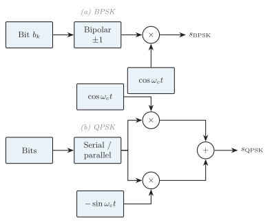
Generation: (a) BPSK maps a bit to and multiplies by the carrier; (b) QPSK splits serial bits into / streams driving two balanced modulators (cosine and sine) whose outputs are summed.
Minimum Shift Keying (MSK)
Section titled “Minimum Shift Keying (MSK)”MSK is continuous-phase binary FSK with modulation index . Using ,
the minimum separation giving orthogonal binary tones while phase accumulates continuously (no jumps at bit boundaries).
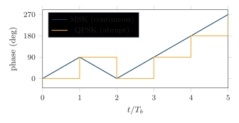
MSK phase evolves as a continuous piecewise-linear trellis ( per bit), whereas QPSK-type modulation makes abrupt phase steps at symbol boundaries.
Properties: carrier phase never jumps; constant envelope allows efficient saturated PAs; lower sidelobes than abrupt FSK; equivalent to OQPSK with half-sinusoidal pulse shaping. GMSK pre-filters data with a Gaussian low-pass filter, narrowing the spectrum at the cost of controlled ISI (set by the time-bandwidth product ); GSM uses GMSK.
Quadrature Amplitude Modulation (QAM)
Section titled “Quadrature Amplitude Modulation (QAM)”QAM independently controls the amplitudes of two orthogonal carriers:
Each pair is one point in the complex constellation.
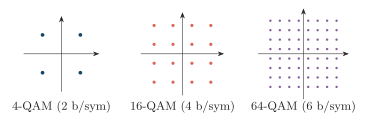
Square constellations of increasing order: as rises the points crowd together at fixed average power, so a larger is needed.
| Scheme | Symbols | Bits/symbol | for |
|---|---|---|---|
| -QAM | 16 | 4 | |
| 64-QAM | 64 | 6 | |
| 256-QAM | 256 | 8 |
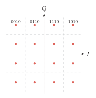
Gray-coded 16-QAM: four levels per axis (), one-bit changes between horizontal/vertical neighbours, and rectangular decision boundaries.
A complete I/Q modem then combines Gray mapping, pulse shaping, quadrature modulation, synchronized reception, and nearest-point decisions.
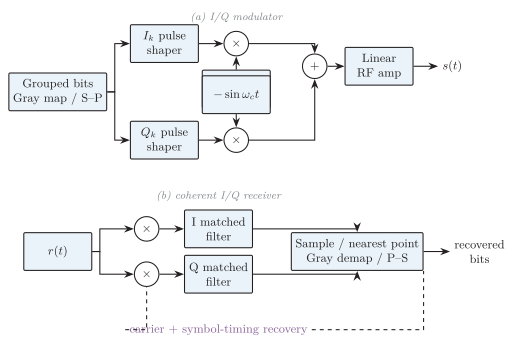
Generic QAM/PSK I/Q modem: Gray mapping and pulse shaping feed the quadrature modulator and linear RF amplifier; after carrier/timing recovery, matched filtering and sampling, the receiver selects the nearest point and Gray-demaps it back to serial bits.
The QAM transmitter groups input bits, applies a Gray constellation mapping, pulse-shapes the resulting and streams, modulates orthogonal carriers, sums them and uses a sufficiently linear RF amplifier. The receiver performs carrier and symbol-timing recovery, coherent I/Q downconversion, matched filtering and symbol-centre sampling; it then chooses the nearest constellation point, Gray-demaps that point and converts the recovered parallel bits to a serial stream.
For raised-cosine roll-off , a common passband estimate is
A high-SNR Gray-coded square-QAM BER approximation is
At fixed power, larger shrinks point spacing, so QAM needs higher SNR and more linear amplification. Uses: digital microwave, cable modems, Wi-Fi/cellular OFDM subcarriers, DVB and adaptive modulation.
Overall Comparison
Section titled “Overall Comparison”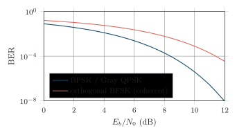
Coherent AWGN BER with equal and matched filtering, sampled from the exact laws (BPSK/Gray QPSK) and (orthogonal BFSK). OOK is omitted because a comparison must first state its energy, prior-probability and threshold normalization.
The plotted comparison assumes AWGN, equal energy per information bit and coherent matched-filter receivers; Gray mapping is assumed for QPSK. It shows only the established laws for BPSK/Gray QPSK and for coherent orthogonal BFSK. OOK is not placed on the same curve ranking because its result depends on how on-symbol versus average bit energy, symbol priors and the decision threshold are normalized.
| Feature | OOK/ASK | Orthogonal BFSK | BPSK |
|---|---|---|---|
| Parameter | Amplitude | Frequency | Phase |
| Envelope | Varies/off | Constant | Constant before filtering |
| Noncoherent option | Envelope det. | Energy det. | Differential (not plain) |
| Coherent AWGN BER | State energy/threshold model | ||
| Bandwidth | Moderate | Widest | Compact |
| PA needs | Linear | Nonlinear OK | Nonlinear OK if controlled |
Binary scheme comparison.
| Scheme | Bits/sym | Spectral eff. | Main strength |
|---|---|---|---|
| BPSK | Moderate | Excellent power efficiency | |
| QPSK | Good | BPSK-like BER at half | |
| MSK/GMSK | Good, compact | Efficient nonlinear PA | |
| -QAM | High | High throughput, moderate SNR | |
| /256-QAM | /8 | Very high | Max throughput on clean channels |
-ary scheme comparison.
Power efficiency (small for a target BER) favours BPSK/QPSK; spectral efficiency (bit/s per Hz) favours higher-order QAM. Improving one usually costs the other, so adaptive systems pick a mode from the channel SNR and amplifier constraints.
Analog Pulse Modulation
Section titled “Analog Pulse Modulation”Pulse modulation varies a parameter of a periodic pulse train according to an analog message; these schemes stay analog until quantisation and coding (PCM) are added.
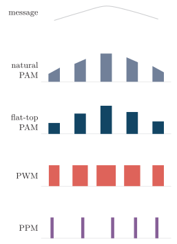
Analog pulse modulation of one message: natural PAM follows the input during each aperture, flat-top PAM holds the sampled level, PWM varies width, and PPM varies position about a timing reference.
| Scheme | Varied parameter | Note |
|---|---|---|
| PAM | Amplitude | Most amplitude-noise sensitive; simplest |
| PWM/PDM | Width/duration | Limiter-friendly; more bandwidth than PAM |
| PPM | Time position | Best amplitude-noise immunity; jitter-sensitive |
In natural PAM, each pulse top follows the input throughout its sampling aperture; flat-top PAM holds one sampled value and is the form presented to practical PCM quantisation. For a comparable pulse rate and fidelity, PWM generally requires more bandwidth than PAM, while PPM usually imposes the greatest timing precision and often the widest pulse spectrum. PWM is commonly generated by comparing the message with a ramp and recovered by integration or low-pass filtering. A PPM receiver establishes the frame reference, measures pulse displacement, converts that position change to a voltage and then filters the result. PPM rejects amplitude disturbances well after limiting, but timing jitter directly corrupts the recovered message.
Spread Spectrum and Multiple Access
Section titled “Spread Spectrum and Multiple Access”Spread spectrum deliberately occupies far more bandwidth than the information signal using a shared pseudorandom pattern; a receiver knowing the pattern despreads the wanted signal.
Multiply each data bit by a much faster bipolar PN chip sequence (chip rate ). The transmitted bandwidth is set mainly by .
The receiver must first acquire the PN-code phase and then track its drift. Correlation with that aligned replica collapses the wanted signal to data bandwidth while narrowband interference is spread and filtered.
A PN generator drives a frequency synthesiser, hopping the carrier among many channels. Slow hopping sends several symbols per hop; fast hopping makes several hops per symbol. FHSS resists narrowband interference and selective fading but needs hop synchronisation and a fast synthesiser.
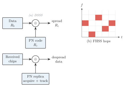
(a) DSSS: a fast PN sequence spreads the data; the receiver acquires and tracks PN phase before correlation with its aligned replica. (b) FHSS: the carrier hops among frequency channels over time under PN control.
Multiple Access
Section titled “Multiple Access”FDMA gives each user a separate frequency channel with guard bands; users transmit simultaneously in different bands. TDMA gives each user a time slot on a shared frequency. CDMA lets users share the same time and band using distinct spreading codes separated by correlation. In a resolvable multipath channel, a rake receiver aligns correlator fingers to delayed replicas and combines them to recover useful multipath energy.
| Feature | FDMA | CDMA |
|---|---|---|
| User separation | Frequency channel | Spreading code |
| Guard resource | Guard bands | Low code cross-corr., power control |
| Capacity | Hard allocation | Interference-limited (soft) |
| Sync | Frequency plan | Code timing, power control |
| Main impairment | Adjacent channel | MAI, near-far problem |