RF Building Blocks: Mixers and PLLs
RF Signal-Chain Context
Section titled “RF Signal-Chain Context”Communication systems partition processing into frequency regions: baseband (message near DC), intermediate frequency (IF) (a fixed band chosen for filtering and gain) and radio frequency (RF) (the transmitted/received carrier band). A frequency converter moves information among these regions: the mixer supplies nonlinear multiplication, the local oscillator (LO) supplies the translation frequency and a filter selects the wanted product.
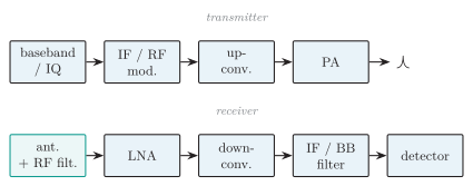
RF signal chain: a transmitter up-converts baseband/IF to RF before the power amplifier; a receiver amplifies, down-converts to a fixed IF/baseband and detects.
Frequency Conversion
Section titled “Frequency Conversion”Frequency conversion translates every spectral component by a controlled amount while ideally preserving relative amplitude, phase and modulation. A mixer combines the input with the LO; sum and difference products appear, and a filter selects the wanted band.
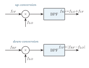
Up-conversion (IFRF) selects the sum product; down-conversion (RFIF) selects the difference product. The same mixer core serves both directions.
Up- and Down-Conversion
Section titled “Up- and Down-Conversion”Mixing with gives products at and ; a bandpass filter selects the desired RF, commonly (transmitter translation, channel allocation, microwave links). The receiver mixes with the LO and selects (superheterodyne reception, spectrum analysers, SDR front ends, channelizers).
Low-Side, High-Side Injection and Spectral Inversion
Section titled “Low-Side, High-Side Injection and Spectral Inversion”Both LO choices (low-side) and (high-side) yield the same IF; the choice affects image location, LO leakage, tuning range and filter design. Selecting a difference product can reverse the order of sidebands (spectral inversion) depending on whether the LO is above or below the signal — critical for SSB and complex I/Q signals.
Mixer Principle
Section titled “Mixer Principle”An ideal mixer is a multiplier. With and , , and using :
The mixer creates both products; a following filter selects one.
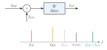
Mixer frequency conversion: and multiply to give (selected) plus the sum, while an image on the opposite side of the LO maps to the same IF.
Real Nonlinear Mixer
Section titled “Real Nonlinear Mixer”A practical device has a nonlinear law with ; cross-products create the spur family:
The wanted conversion is a low-order product; the rest are spurs needing frequency planning and filtering. The RF port carries the signal band, the LO port a strong switching/pump waveform and the IF port the translated band; a passive reciprocal mixer can often convert in either direction.
Passive and Active Mixers
Section titled “Passive and Active Mixers”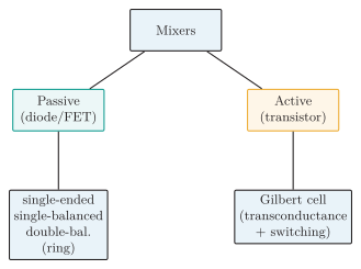
Mixer classification: passive diode/FET topologies (single-ended, single-balanced, double-balanced/ring) versus active transistor mixers such as the Gilbert cell. Passive NF is approximately conversion loss plus excess noise; active mixers can provide gain but add device noise and may have a lower high-frequency limit.
Passive mixers use diodes or MOSFETs as LO-driven switches (single diode, diode ring, FET commutating). They need no DC core power, usually show conversion loss, offer good linearity and large-signal handling, require high LO drive, and (double-balanced) suppress LO/RF feedthrough. For a passive mixer at the standard noise temperature, noise figure in dB is approximately its conversion loss plus practical excess noise, subject to the stated SSB/DSB convention. Active mixers (e.g. Gilbert cell) use biased transconductance plus switching: they can provide conversion gain, accept lower LO drive and integrate well with LNA/IF stages, but consume DC power, add device noise and often have lower linearity/dynamic range; transistor speed and parasitics can also limit their highest useful frequency range.
| Feature | Passive mixer | Active mixer |
|---|---|---|
| DC power | None / very low in core | Required (bias) |
| Conversion | Loss | Gain or lower loss possible |
| LO drive | Usually higher | Often lower |
| Linearity | Often higher | Often lower |
| Integration | Baluns awkward | Excellent in ICs |
| Noise | Loss directly hurts cascaded NF | Device noise, but gain helps |
Passive versus active mixer trade-offs.
Balance types: unbalanced (simplest, large feedthrough); single-balanced (symmetry suppresses one feedthrough family); double-balanced (ideally suppresses both RF and LO feedthrough and even-order products). No practical balance is perfect due to device/transformer mismatch.
Mixer Performance and Nonidealities
Section titled “Mixer Performance and Nonidealities”These equations use a power-conversion convention. A quoted mixer result must state whether it is power or voltage conversion and, for power, whether available or transducer gain/loss is meant. It must also give the defining test conditions: RF/IF frequencies and terminations, LO frequency and drive, RF input level, and relevant bandwidth/temperature for noise measurements.
Port isolation is the attenuation of unwanted leakage between ports (LORF limits LO radiation from the antenna; LOIF limits LO feedthrough; RFIF measures direct leakage). Higher isolation in dB is better.
-
Noise figure: ; image-band noise can convert to IF, so single- vs double-sideband NF must be stated.
-
-dB compression point (): input/output power where actual conversion gain falls below the small-signal extrapolation — onset of large-signal compression, not an operating point.
-
Third-order intercept (IIP3/OIP3): two tones create in-band and ; extrapolated fundamental and IM3 lines meet at the intercept. Higher IP3 better linearity, but it is extrapolated.
-
Spurious/image: any input with maps to IF; the ordinary image is the term on the opposite side of the LO. Preselection and multiple conversion reduce responses.
Phase-Locked Loop (PLL)
Section titled “Phase-Locked Loop (PLL)”A PLL is a negative-feedback system that adjusts a voltage-controlled oscillator (VCO) so its output phase/frequency follows a reference. It comprises a phase detector, loop filter and VCO, with optional feedback division.
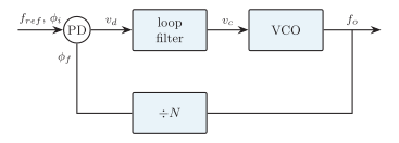
PLL core: the phase detector (PD) compares reference and feedback phase; the loop filter averages the error; the VCO output is fed back (optionally ) to close the loop.
| Block | Function |
|---|---|
| Phase detector / PFD | Compare reference and feedback phase; produce error |
| Charge pump (digital PLL) | Convert PFD pulses to controlled current |
| Loop filter | Average error, reject detector products, set loop dynamics |
| VCO | Produce frequency controlled by loop voltage |
| Divider (, optional) | Scale output before comparison for synthesis |
PLL building blocks.
where is detector gain (V/rad) and is VCO sensitivity (Hz/V).
Operating States
Section titled “Operating States”-
Free-running: without useful error, the VCO runs near .
-
Acquisition/capture: average correction pulls the VCO toward the input.
-
Locked: average frequencies are equal (or follow the divider ratio). Phase error is bounded and constant for a static offset.
-
Loss of lock: input change, noise or modulation exceeds tracking/hold capability.
Capture and Lock Ranges
Section titled “Capture and Lock Ranges”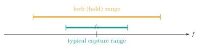
Typical PLL relation: the capture range (acquire from unlocked) is smaller than the lock/hold range (remain locked). Exact definitions and limits depend on detector, loop topology and test method.
The capture range is where an unlocked PLL can acquire lock; the lock/hold/tracking range is where an already-locked loop stays locked as the input changes slowly.
Loop Bandwidth Trade-Off
Section titled “Loop Bandwidth Trade-Off”Wider loop bandwidth tracks faster modulation and acquires quickly but passes more noise/spurs; narrower bandwidth filters noise but acquires/tracks slowly. Loop damping sets overshoot, settling and stability. A first-order loop has no independent filter pole; second-order loops (most common) trade bandwidth against damping.
PLL Applications
Section titled “PLL Applications”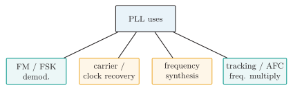
PLL applications span demodulation, synchronization, synthesis, tracking and multiplication. For AFC, filtered control voltage corrects slow local-oscillator drift.
FM/FSK Demodulation
Section titled “FM/FSK Demodulation”The VCO control voltage tracks instantaneous input frequency, so the loop-filter output is the recovered message:
For FSK, the control voltage settles to two levels (mark/space); a threshold recovers bits if both tones lie in the tracking range and the symbol duration is long enough for the loop to settle sufficiently before the decision instant.
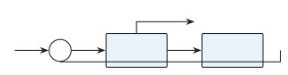
PLL as an FM demodulator: the recovered message is taken as the loop-filter control voltage that forces the VCO to follow the input.
Carrier and Clock Recovery
Section titled “Carrier and Clock Recovery”Suppressed-carrier DSB/PSK needs a coherent reference: a Costas loop uses I/Q products to form a data-insensitive phase error; a squaring loop makes a carrier multiple then divides; a pilot-aided loop locks to a transmitted pilot. BPSK’s ambiguity is handled by differential coding or training. Clock recovery uses a timing-error detector plus loop filter and controlled oscillator to place sampling instants at symbol centres (a timing PLL, even when digital).
Frequency Synthesis and Multiplication
Section titled “Frequency Synthesis and Multiplication”With a reference divider, define . Inserting in feedback gives, in lock, , so ; changing integer selects channels spaced by . A feedback divider multiplies by ; a divider after the VCO yields coherent lower frequencies. Frequency multiplication scales carrier frequency, frequency deviation and phase deviation by the multiplication factor. Reference-derived phase noise rises ideally by in dB, and practical PLL output also contains loop, divider and VCO noise.
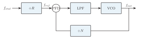
Integer- frequency synthesizer: reference , PFD, loop filter, VCO and feedback give .
The basic integer- channel step is . Fractional- synthesis modulates the divider sequence so its average ratio is fractional, giving finer channel steps. Divider quantization then creates shaped noise and fractional spurs; the modulation pattern and PLL bandwidth/loop filter must be chosen together to trade settling, in-band noise and spur suppression.
Tracking Filter and AFC
Section titled “Tracking Filter and AFC”A narrow PLL can act as a tracking filter: it follows the wanted carrier inside its loop bandwidth while rejecting more distant out-of-band noise and interference. In automatic frequency control (AFC), the filtered control/error voltage is fed to the receiver local oscillator so that slow LO drift is corrected and the wanted signal remains centred in the IF passband.