Transformers, Generators and Induction Motors
Transformer
Section titled “Transformer”A transformer is a static device that transfers AC power between two circuits at the same frequency by mutual induction, usually changing the voltage level, with no electrical connection between windings.

Core-type single-phase transformer: primary and secondary windings on a laminated core linked by mutual flux .
| Part | Construction and function |
|---|---|
| Magnetic core | Laminated CRGO silicon-steel limbs/yokes: low-reluctance flux path; thin laminations cut eddy currents |
| Primary | Turns fed by the AC source; sets up the alternating mutual flux |
| Secondary | Links the same flux and supplies the isolated load |
| Tank, oil, radiators | Insulate and remove heat in oil-filled power units |
| Conservator, breather, Buchholz | Allow oil expansion, exclude moisture, detect gas faults |
Transformer construction (core-type: windings around limbs; shell-type: core around the windings).
step-up, step-down; ideally (the ).
| Loss | Depends on | Reduced by |
|---|---|---|
| Hysteresis | Voltage/frequency (nearly constant) | Low-loss CRGO steel |
| Eddy current | Voltage/frequency (nearly constant) | Thin insulated laminations |
| Copper | Square of load | Larger conductor area, cooling |
Transformer losses (iron loss hysteresis eddy).
is maximum when copper loss core loss (95–99%, no rotating parts). An open-circuit test gives core loss; a short-circuit test gives full-load copper loss and series impedance. Types: power, distribution, autotransformer (single winding, saves copper), instrument (CT, PT) and isolation () transformers.
DC Generator
Section titled “DC Generator”Converts mechanical energy to DC by Faraday’s law (); the commutator acts as a mechanical rectifier turning the internal AC into unidirectional output. Direction: Fleming’s right-hand rule.
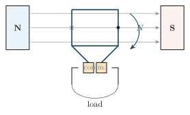
Single-loop DC generator: a coil rotates in the pole flux; the split commutator and brushes deliver DC to the load.
| Part | Function |
|---|---|
| Yoke | Mechanical frame and low-reluctance flux return path |
| Pole core / shoe | Carry field coils; spread flux across the air gap |
| Field winding | Produces the stationary main field |
| Armature (laminated) | Rotating slotted core; laminations cut eddy loss |
| Commutator | Mica-insulated copper segments; rectify armature AC |
| Brushes | Sliding carbon contacts collecting the DC output |
DC generator (and motor) construction.
poles, flux/pole (Wb), conductors, speed (rpm), parallel paths. Lap () gives many low-voltage/high-current paths; wave () gives high-voltage/low-current.
| Type | Field connection | Feature / use |
|---|---|---|
| Separately excited | External DC source | Wide voltage control; testing |
| Shunt | Field armature | Near-constant ; battery charging |
| Series | Field in series | rises with load; boosters |
| Compound | Shunt series | Flat regulation; general supply |
DC generator types by excitation.
Armature reaction: the armature flux distorts and weakens the main field and shifts the neutral axis; commutation: is the current reversal in a coil at the brush. Both are improved by interpoles and compensating windings (with correct brush position).
DC Motor
Section titled “DC Motor”A current-carrying conductor in a field feels (Fleming’s left-hand rule). Rotation generates a back-EMF opposing the supply, making the motor self-regulating.
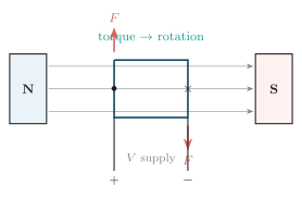
DC motor: field armature current gives conductor forces and torque; the rotating armature develops a back-EMF .
At starting , so is dangerously large — a starter or electronic current limiter is required. Self-regulation: more load slower smaller larger more torque.
| Motor | Characteristic | Application |
|---|---|---|
| Shunt | Near-constant flux and speed | Fans, lathes, pumps |
| Series | Very high starting torque (never unloaded) | Cranes, traction, hoists |
| Compound | Good starting torque better speed regulation | Elevators, presses |
DC motor types.
Speed control: flux control (field rheostat), armature-resistance control, and armature-voltage control (Ward–Leonard / chopper).
AC Machines
Section titled “AC Machines”Both AC machines use the rotating field set up by balanced three-phase stator currents, turning at the synchronous speed .
A three-phase induction motor induces current in its cage/wound rotor; the rotor runs below with slip (typically 2–5%, rotor-current frequency ) and is self-starting ( at standstill). A synchronous motor locks to (zero steady slip), is not self-starting, and when over-excited supplies leading VAR (synchronous condenser). An alternator generates 3 AC with a DC-excited rotor, its frequency locked to speed by .
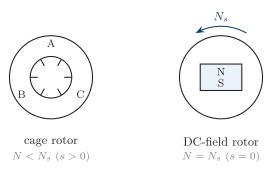
Both machines use a rotating stator field; the induction rotor slips below , the synchronous rotor locks to .
| Feature | Induction motor | Synchronous motor |
|---|---|---|
| Rotor excitation | Induced (cage rotor) | DC or permanent magnet |
| Running speed | Below (slips with load) | Exactly to pull-out |
| Starting | Self-starting (3) | Needs a starting arrangement |
| Power factor | Lagging | Adjustable (lag/unity/lead) |
| Use | Pumps, fans, compressors | Constant-speed drives, PF correction |
Induction versus synchronous motor.
| Feature | DC machine | Induction machine |
|---|---|---|
| Supply | DC | AC |
| Commutator | Yes (maintenance) | No |
| Speed control | Easy, wide range | Needs a VFD |
| Robustness / cost | Lower / higher | Very rugged / lower |
DC versus AC machines.