Transmission Fundamentals
Evolution of Telecommunication Systems
Section titled “Evolution of Telecommunication Systems”Digitisation enabled regeneration, multiplexing, and software-controlled switching. Packet networks then allowed voice, data, and video to share transport capacity instead of requiring separate service networks.
| Stage | Main technology | Key feature |
|---|---|---|
| Telegraph era | Wired telegraph | Text signalling via electrical pulses |
| Manual telephony | Magneto exchange | Operator-assisted circuit connection |
| Automatic telephony | Strowger, crossbar | Dial-based automatic connection |
| Analog transmission | FDM, coax, microwave | Voice carried as analog channels |
| Digital transmission | PCM, TDM, PDH, SDH | Voice digitised and multiplexed |
| Data networks | X.25, Frame Relay, IP | Efficient bursty data transfer |
| Mobile networks | 1G – 5G | Cellular mobility and broadband access |
| NGN | IP/MPLS, softswitch, IMS | Converged voice, data and video over IP |
Evolution of telecommunication systems
Basic Telecommunication Network
Section titled “Basic Telecommunication Network”A telecommunication network is a collection of terminals, transmission links, switching nodes and signalling systems used to transfer information from one point to another.
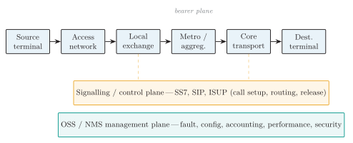
Architecture of a telecommunication network.
| Element | Function | Example |
|---|---|---|
| Terminal | Converts user info to electrical/optical/radio signal | Phone, router |
| Transmission medium | Carries the signal between nodes | Fiber, microwave |
| Switching node | Selects path and connects users | Exchange, router |
| Signalling system | Controls setup, routing, charging, release | SS7, SIP |
| Network management | Fault, config, accounting, performance, security | NMS/OSS |
Main elements of a telecommunication network
-
Network hierarchy:
-
Access links connect subscribers to the provider through copper loops, FTTH, or cellular radio.
-
Aggregation combines access traffic on regional links, such as metro Ethernet or SDH rings.
-
The core carries aggregate traffic between regions using high-capacity optical and IP/MPLS transport.
-
-
Topology: Star and tree structures concentrate traffic economically but depend on central nodes. Rings and meshes offer alternate paths when protection or routing mechanisms are provided, at the cost of additional links and control complexity.
Transmission Media
Section titled “Transmission Media”-
Guided: Twisted pair, coaxial cable, and optical fibre constrain signal propagation to a conductor arrangement or dielectric waveguide.
-
Unguided: Radio and optical wireless systems transmit electromagnetic energy through free space between antennas or optical terminals.
| Guided medium | Use | Trade-off |
|---|---|---|
| Twisted pair | Telephone loop, DSL, Ethernet | Cheap; noise, crosstalk, attenuation |
| Coaxial cable | CATV, RF feeders, legacy trunk | Good shielding; bulkier, costlier |
| Optical fiber | Backbone, FTTH, submarine | Low loss, huge BW, EMI-immune; splicing cost |
Guided transmission media
-
Radio propagation: Diffraction, reflection, ground-wave, or ionospheric propagation can support non-line-of-sight reception in suitable bands. Fixed microwave links usually require line of sight and Fresnel-zone clearance.
-
Satellite: Provides wide-area coverage; GEO links incur substantial propagation delay because of their long Earth–satellite paths.
-
Infrared: Supports short-range optical wireless links but generally cannot pass through opaque walls.
-
Selection: Required rate, distance, attenuation, interference, availability, installation cost, and spectrum regulation determine which medium is suitable.
Transmission Lines
Section titled “Transmission Lines”-
Propagation delay: Distributed-line analysis is needed when delay is appreciable relative to the signal period or rise time. A sinusoidal line length near is a common guideline.
-
Per-unit-length constants: and model series conductor resistance and inductance; and model shunt capacitance and dielectric leakage.
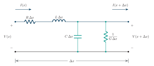
Equivalent circuit of a transmission-line section.
Here is attenuation in Np/m, is phase change in rad/m, and is angular frequency in rad/s.
Characteristic Impedance and Matching
Section titled “Characteristic Impedance and Matching”Characteristic impedance is the voltage-to-current ratio of a forward travelling wave. It is also the input impedance of an infinitely long uniform line, or a finite line terminated in . A load produces no reflection.
| Condition | Result | |
|---|---|---|
| (match) | No reflection, VSWR | |
| Open circuit | Full reflection, same polarity | |
| Short circuit | Full reflection, opposite polarity |
Load matching suppresses reflections, standing waves, and reflection-related echo, reducing power returned toward the transmitter. Maximum available power from a source additionally depends on matching at the source port.
Return Loss
Section titled “Return Loss”Transformers and the Hybrid Circuit
Section titled “Transformers and the Hybrid Circuit”-
Coupling and isolation: A transformer transfers AC energy magnetically while isolating the DC paths. Winding configuration can provide impedance transformation and balanced-to-unbalanced conversion.
-
Turns ratio: Let . For an ideal transformer, voltage and current magnitudes and the secondary load referred to the primary satisfy:
A secondary load appears as at the primary when , so the required primary-to-secondary turns ratio is .
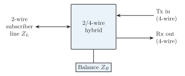
Two-wire to four-wire hybrid circuit.
-
Two-wire/four-wire conversion: A subscriber pair carries both directions on the same two conductors. A hybrid couples it to separate transmit and receive paths, allowing independent amplification and digital processing in the two directions.
-
Balance: A balancing impedance approximates the two-wire line impedance over the speech band. The hybrid cancels the component that would otherwise leak from the incoming four-wire path into the outgoing path.
-
Trans-hybrid loss: High loss between these two four-wire ports means good isolation. An impedance mismatch weakens cancellation, returning part of the incoming signal as electrical echo.
Signal Level and Noise Measurements
Section titled “Signal Level and Noise Measurements”Echo and Singing
Section titled “Echo and Singing”-
Echo: A delayed copy of speech returns through an electrical reflection or acoustic coupling path.
-
Talker echo returns to the original speaker. Listener echo reaches the listener as a delayed duplicate after additional reflections.
-
Poor hybrid balance causes electrical echo; loudspeaker-to-microphone coupling causes acoustic echo.
-
Audibility depends on both echo delay and attenuation. Longer delays generally require greater echo attenuation; there is no universal acceptable-delay threshold independent of echo level.
-
Matching and balancing reduce the echo path. An echo suppressor attenuates a direction when appropriate; an adaptive echo canceller estimates the echo from a reference signal and subtracts it, allowing simultaneous speech.
-
-
Singing: Excess gain and leakage through hybrids can close a positive-feedback loop around the four-wire path. A small disturbance grows into an audible oscillation when the loop gain exceeds unity at a frequency with reinforcing phase. Reducing gain and improving hybrid isolation restore a stability margin.
| Feature | Echo | Singing |
|---|---|---|
| Nature | Delayed reflected speech | Continuous oscillation/howl |
| Main cause | Reflection (mismatch) | Positive feedback, high loop gain |
| Delay-sensitive | Yes | Not mainly |
| Control | Cancellation, matching | Reduce gain, improve balance |