Sequence Generators
A sequence generator is a clocked circuit whose outputs pass through a prescribed repeating sequence. It may use a feedback shift register, a counter plus decoder or memory, or general next-state logic.
For the shift convention used here,
Writing the update equation avoids ambiguity about the words “left” and “right.”
Shift-Register-Based Generators
Section titled “Shift-Register-Based Generators”Ring generator
Section titled “Ring generator”A ring generator feeds the last-stage output back without inversion:
With a one-hot initial state,
An -stage ring has useful states. Its outputs directly provide one-hot phases, but the all-zero state is locked and initialization must load exactly one 1.
Johnson generator
Section titled “Johnson generator”A Johnson or twisted-ring generator feeds back the complement:
Starting from zero,
An -stage Johnson generator has valid states.
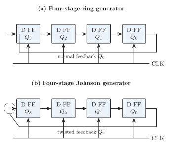
Feedback-register realizations of ring and Johnson sequence generators.
| Property | Ring | Johnson |
|---|---|---|
| Feedback | ||
| Useful states with FFs | ||
| Pattern | One-hot bit circulates | 1s fill, then 0s fill |
| Initialization | Preset one-hot word | Clear to zero |
| Decoding | Direct output | Two-input phase decoding |
| Risk | Zero lock or multiple circulating 1s | Invalid cycles |
| Use | One-hot timing and scanning | Multi-phase timing and control |
Ring and Johnson generators compared.
Only of the possible Johnson states belong to the intended cycle. Reset or recovery logic is required when deterministic startup matters.
Linear-Feedback Shift Register
Section titled “Linear-Feedback Shift Register”An LFSR forms the serial input by XORing selected stage outputs. If the feedback polynomial is primitive and the seed is nonzero, an -stage LFSR visits every nonzero state once:
The all-zero state is locked because XOR of zeros remains zero.
For the primitive polynomial , use
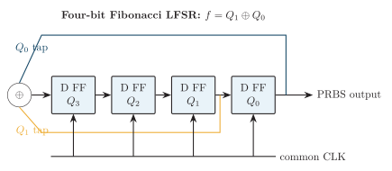
Four-bit maximal-length LFSR realization.
Starting from 0001, the state sequence is
The period is 15. The sequence is deterministic and is not cryptographically secure by itself. LFSRs are used for test patterns, scrambling, CRC hardware, spread-spectrum sequences and built-in self-test.
Counter-Based Sequence Generation
Section titled “Counter-Based Sequence Generation”A binary or mod- counter can serve as a sequence address. A decoder asserts one timing output per count, while a ROM or combinational block maps each count to an arbitrary output word:
For a sequence of stored words, the address counter needs at least bits. This method is direct and easy to modify, but it uses more decoding or storage hardware than a short feedback pattern.
Design of a Required Sequence
Section titled “Design of a Required Sequence”For a repeating sequence of states:
-
assign a binary code to every required state;
-
write the present-state/next-state table, including unused-state policy;
-
choose flip-flops and derive their excitation or D-input equations;
-
simplify each equation and draw the common-clock circuit;
-
trace one full cycle plus every unused starting state.
Example: two-bit Gray sequence
Section titled “Example: two-bit Gray sequence”Generate
With two D flip-flops, the next-state table gives
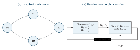
Design of the repeating two-bit Gray sequence. The next-state logic changes exactly one state bit on each clock edge.
Substitution verifies every transition. All four two-bit states are used, so there is no unused-state recovery case. If only an output waveform rather than the state word is required, decode the desired states after the register.
| Method | Strength | Limitation |
|---|---|---|
| Ring | Direct one-hot phases | Only states from flip-flops |
| Johnson | easily decoded phases | Invalid states need attention |
| LFSR | Period up to with few gates | Fixed pseudorandom order; zero lock |
| Counter + decoder/ROM | Arbitrary output sequence | Extra decoder or memory |
| Custom state machine | Arbitrary conditional sequence | Full state design required |
Choosing a sequence-generator method.