Splices, Connectors, Networks, Switching, Submarine Cable
Optical Connectors
Section titled “Optical Connectors”A connector is a detachable precision alignment between fibre end faces and equipment or another fibre.
| Connector | Feature | Common use |
|---|---|---|
| SC | Push–pull square | Telecom, FTTH |
| LC | Small-form-factor latch | High-density panels, SFPs |
| ST | Bayonet twist | Older LAN systems |
| FC | Threaded | Test gear, high vibration |
| MPO/MTP | Multi-fibre ribbon | Data centres |
Common fibre connectors.
Connector losses arise from lateral and angular misalignment, end separation, end-face defects, core/NA mismatch and Fresnel reflection.
Low and high (low reflection) are desirable.
Fibre Splicing
Section titled “Fibre Splicing”Splicing permanently joins two fibres.
-
Fusion splice: strip, clean, cleave, align, arc-fuse, protect, test. Lowest loss/reflection, high strength; needs an expensive splicer.
-
Mechanical splice: cleaved ends held in an alignment fixture with index-matching gel. Quick and cheap; higher loss/reflection, for temporary restoration.
| Feature | Fusion splice | Mechanical splice |
|---|---|---|
| Joint | Permanently fused glass | Mechanical alignment |
| Typical loss | Very low | Higher |
| Reflection | Very low | Higher |
| Equipment cost | High | Low |
| Reliability | High | Moderate |
| Use | Long-haul, FTTH, permanent | Temporary/quick repair |
Fusion versus mechanical splicing.
Optical Time-Domain Reflectometer (OTDR)
Section titled “Optical Time-Domain Reflectometer (OTDR)”An OTDR locates faults and measures loss/length by launching a pulse and recording Rayleigh backscatter plus Fresnel reflections versus time.
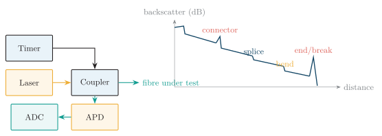
OTDR: pulse launched through a coupler; the backscatter trace shows a sloped fibre loss, a reflective connector spike, a non-reflective splice step, a bend step and a strong end/break reflection.
The dead zone after a strong reflection hides nearby events; it is reduced with a shorter pulse and a launch fibre. Longer pulses give more range but poorer resolution.
Optical Link Budgets
Section titled “Optical Link Budgets”Power Budget
Section titled “Power Budget”The power-budget staircase tracks each loss and design margin from transmitter output to the receiver-sensitivity threshold.
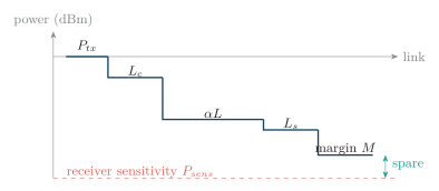
Power-budget staircase: transmitter power minus connector, fibre, splice, and margin losses must leave above receiver sensitivity.
Rise-Time Budget
Section titled “Rise-Time Budget”A link can pass the power budget yet fail the timing budget (ISI), so both must be checked.
Optical Networks, Switching and Submarine Cable
Section titled “Optical Networks, Switching and Submarine Cable”-
PON / access networks: a passive splitter shares one feeder fibre among many subscribers (FTTH); no active elements in the outside plant.
-
WDM/DWDM backbone: many wavelengths per fibre multiply capacity; optical amplifiers (EDFA) replace electrical repeaters.
-
Optical switching: routes light without O/E/O conversion (wavelength/space switching, ROADMs); lowers latency and power.
-
Submarine cable: inter-continental fibre with periodic optical repeaters/EDFAs and robust armouring, powered over a copper conductor.