An analog filter passes a prescribed frequency band and attenuates frequencies outside it. An active filter combines resistors and capacitors with an amplifying device, normally an op-amp, to provide gain and buffering without inductors. The order n is the highest power of s in the denominator and, equivalently, the number of poles; larger n gives a sharper transition.
Active filters offer voltage gain, high input impedance, low output impedance, easy cascading and practical low-frequency realization. Their limits are the op-amp GBW, slew rate, noise, output range and the tolerances of R and C.
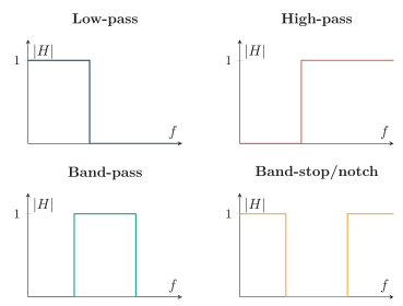
Idealized low-pass, high-pass, band-pass and band-stop responses.
The passband meets the allowed attenuation or ripple; the stopband meets a minimum attenuation; the region between them is the transition band. At a Butterworth cutoff, the magnitude is 1/2 of passband gain, or −3.01dB. Each pole ultimately contributes 20dB/decade (6dB/octave) attenuation.
For a band-pass response,
BW=fH−fL,f0=fLfH,Q=BWf0.
The geometric-center relation is exact for the standard second-order form.
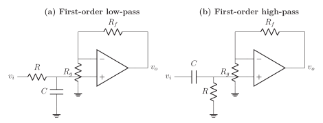
At fc, both magnitudes are K/2. The low-pass phase changes from 0∘ toward −90∘ and rolls off at −20dB/decade; the high-pass rises at +20dB/decade below cutoff and approaches K with phase tending to 0∘ above cutoff.
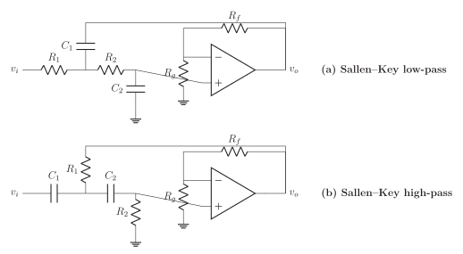
With equal R1=R2=R, C1=C2=C, both dual circuits have
ω0=RC1,Q=3−K1.
Thus an equal-component second-order Butterworth section needs Q=1/2, hence K=3−2≃1.586. A unity-gain equal-component section has Q=0.5, not the Butterworth value.
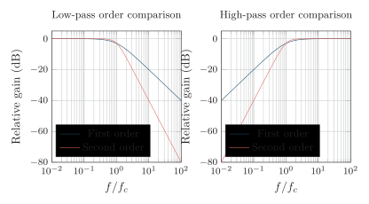
First- and second-order asymptotic behavior: 20 and 40dB/decade.
A practical wideband active band-pass may cascade a first-order high-pass at fL and a first-order low-pass at fH; buffering prevents interaction:
H(s)=Ks+ωLss+ωHωH,ωL<ωH.
This is second order overall. For a narrow, high-Q band, use the standard second-order band-pass form above in a multiple-feedback or state-variable realization, because widely separated one-pole sections cannot produce high selectivity.
Buffered second-order wideband band-pass and its practical transmission specifications.
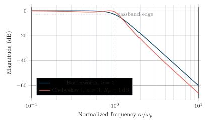
A Type-I Chebyshev filter accepts controlled equal ripple in the passband to obtain a sharper transition than a Butterworth filter of the same order. Its normalized low-pass magnitude is
∣HC(jω)∣2=1+ε2Tn2(ω/ωp)1,ε=10Rp/10−1,
where Rp is passband ripple in dB and
Tn(x)=cos(ncos−1x),∣x∣≤1,Tn+1=2xTn−Tn−1.
The first polynomials are T0=1, T1=x, T2=2x2−1 and T3=4x3−3x. Type I has a monotonic stopband and generally more nonlinear phase/group delay than Butterworth. Type II (inverse Chebyshev) instead has a flat passband and equiripple stopband.