Data Communication and Networking
Data Communication Basics
Section titled “Data Communication Basics”Data communication is the exchange of digital data between two or more devices through a transmission medium, governed by agreed protocols.
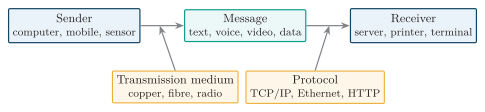
Basic data communication system.
| Data-flow mode | Direction | Example |
|---|---|---|
| Simplex | One-way only | Radio/TV broadcast |
| Half-duplex | Both ways, not simultaneously | Walkie-talkie |
| Full-duplex | Both ways at once | Telephone, switched Ethernet |
Data-flow (transmission) modes
-
Line configuration:
-
Point-to-point: A link connects exactly two devices, as in a leased line or an Ethernet link between a host and a switch.
-
Multipoint: Several devices share one link and need a medium-access method to coordinate transmissions, as in a Wi-Fi channel or a bus network.
-
-
Transmission form:
-
Parallel: Several bits travel simultaneously on separate conductors. Wiring cost and timing skew between conductors limit the practical distance.
-
Serial: Bits travel sequentially over a channel. It needs fewer conductors and is widely used for both short- and long-distance links.
-
-
Serial timing:
-
Asynchronous: Each character has a start bit, data bits, optional parity, and one or more stop bits. The start bit resynchronises the receiver; gaps between characters may vary.
-
Synchronous: Bits are sent in frames or blocks using a shared or recovered clock. Frame boundaries are identified by framing information, without start and stop bits around every character.
-
Performance Terms
Section titled “Performance Terms”Bit Rate, Baud Rate, and Symbol Content
Section titled “Bit Rate, Baud Rate, and Symbol Content”-
Signal alphabet : Number of distinguishable symbols available, such as the 16 amplitude/phase combinations in 16-QAM.
-
Bits per symbol : A fixed-length binary mapping needs symbols to represent all -bit combinations.
-
Symbol rate : Number of symbols transmitted per second, measured in baud. It is not the number of signal transitions: consecutive symbols may be identical.
-
Bit rate : Gross number of encoded bits transmitted per second. Coding redundancy and protocol overhead reduce the useful information rate below this value.
Example: A 16-QAM modem sends symbols/s. Each symbol carries bits, giving
Throughput and Goodput
Section titled “Throughput and Goodput”Throughput depends on the layer at which delivery is measured. For a delivery-based measurement over seconds, let be the unique application payload bits successfully received and the protocol overhead included with those counted deliveries. Count each delivered data unit once, excluding failed and duplicate copies.
-
Overhead: Headers and trailers counted at the chosen layer contribute to throughput but not to application goodput. An application-level throughput measurement may therefore be the same as goodput.
-
Retransmission: Repeated copies consume link time without creating new application data. A successful retransmission contributes previously missing payload once; duplicates do not contribute again.
-
Rate comparison: For the same single link, interval, and bit-counting basis, without compression,
Dividing all transmitted bits by measures the attempted transmission rate, not necessarily successful throughput.
Example: Over s on a 12 Mbit/s link, a receiver obtains 18 Mbit of unique payload and 2 Mbit of associated overhead. Then
Bandwidth and Shannon Capacity
Section titled “Bandwidth and Shannon Capacity”Physical bandwidth is the occupied or available frequency range,
measured in Hz, not bit/s. For an ideal band-limited channel with additive white Gaussian noise (AWGN), the Shannon–Hartley theorem gives the information-rate limit.
-
is channel capacity in bit/s; is channel bandwidth in Hz.
-
and are received signal and noise powers in the same bandwidth. Their ratio must be linear, not in decibels:
- Rates below can theoretically achieve arbitrarily small error probability with suitable coding. Capacity is not a guaranteed application rate; practical coding, receivers, and protocol overhead limit achievable goodput.
Example: For kHz and an SNR of 30 dB, , so
Bit Error Rate
Section titled “Bit Error Rate”An empirical BER compares the received test sequence with a known transmitted sequence. If bit decisions are incorrect among compared bits,
The ratio is dimensionless and estimates the probability of a bit error. Lost packets are a separate measurement, not automatically a known number of wrong bit decisions.
Example: 25 errors in compared bits give .
For uncoded BPSK with coherent detection in AWGN, equally likely bits, and no intersymbol interference, the theoretical bit-error probability is
-
is received energy per bit in joules; is the one-sided noise power spectral density in W/Hz. The ratio is dimensionless and must be linear in this formula.
-
is the complementary error function. Increasing reduces the probability that noise makes the receiver choose the wrong BPSK symbol.
-
The formula is specific to these modulation and channel assumptions. Coding, fading, interference, or a different modulation scheme changes the BER relation.
Latency and End-to-End Delay
Section titled “Latency and End-to-End Delay”-
Processing delay : Time spent checking headers, performing lookups, and preparing a packet for forwarding; it depends on the device and workload.
-
Queuing delay : Time waiting for service in buffers. It depends on traffic bursts, offered load, scheduling, and service rate; it is not a fixed property of the cable.
-
Transmission delay: Time to place a packet’s bits onto a link of rate :
Use the number of bits actually serialised at the boundary being measured, including the relevant headers and trailers.
- Propagation delay: Time for a signal to travel distance through a medium at speed :
In fibre, is approximately m/s. Increasing the link bit rate reduces transmission delay, but does not reduce propagation delay.
For store-and-forward hops, sum each hop’s processing, queuing, transmission, and propagation delays:
In the ideal queuing model, arrivals are Poisson, service times are exponential, and there is one server. With arrival rate and service rate in packets/s, the mean waiting time before service is
This is an average under those assumptions, not the delay of every packet. It grows sharply as the arrival rate approaches the service rate.
Example: A 12,000-bit packet on a 10 Mbit/s link takes ms to transmit. Over 1000 km of fibre, propagation takes ms. With ms processing and ms queuing,
Jitter and the RTP Estimate
Section titled “Jitter and the RTP Estimate”Jitter measures variation in packet delay, not the delay itself. If is the one-way delay of packet , one measure is the absolute delay difference between consecutive packets:
- RTP measurement: For consecutive packets in reception order, use arrival times and RTP timestamps , both expressed in the same RTP clock units:
This measures variation in relative transit time. A constant offset between sender and receiver clocks cancels; simply comparing arrival times without subtracting timestamp spacing would include the source’s packet spacing.
-
Units: RTCP reports in RTP timestamp units. Divide by the RTP clock rate to obtain seconds. This smoothed absolute variation is not statistical variance, which would have units of time squared.
-
Playout buffering: A receiver can absorb delay variation by waiting before playing media, but a larger buffer increases playout latency.
Example: Consecutive delays of 20 ms and 26 ms give ms. If the previous estimate is 4 ms, the updated estimate, expressed in milliseconds, is
Switching Techniques
Section titled “Switching Techniques”Switching connects a source to a destination through intermediate nodes. Circuit switching reserves a circuit; message switching forwards whole messages; packet switching forwards smaller units that share link capacity.
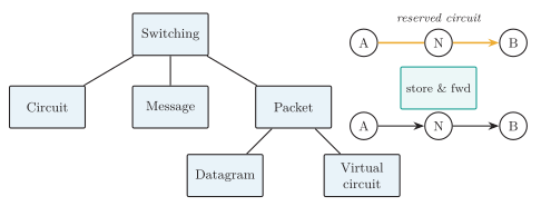
Circuit, message and packet switching.
Circuit switching
Section titled “Circuit switching”-
Operation: The network establishes an end-to-end circuit before data transfer and reserves capacity on each link until release. The reservation may be a frequency band or recurring time slot, not a separate wire.
-
Phases: Circuit establishment data transfer circuit release.
-
Advantages: Reserved capacity and predictable delay after setup suit continuous, real-time traffic such as a PSTN voice call.
-
Limitations: Setup adds delay; a call is blocked if resources are unavailable. Reserved capacity remains unavailable to other users even while the source is silent, making circuit switching inefficient for bursty data.
Message switching
Section titled “Message switching”-
Operation: Each intermediate node receives and stores the entire addressed message before forwarding it when an outgoing link becomes available. No end-to-end circuit is reserved.
-
Advantages: Links carry messages from different users as capacity becomes available. Queued messages can be prioritised or held until a busy link is free.
-
Limitations: Every hop must buffer a complete message. Long messages require large storage and introduce substantial store-and-forward and queuing delay, so the method is unsuitable for real-time voice or video.
Packet switching
Section titled “Packet switching”-
Operation: A message is divided into packets, each with a control header. Nodes forward packets over shared links; forwarding can begin before the entire message has arrived.
-
Datagram mode: Each packet carries a destination address and is forwarded independently. Packets may follow different routes and arrive out of order. IP uses this mode.
-
Virtual-circuit mode: A logical path and forwarding state are established before transfer. Packets carry a short connection identifier and normally follow the same path in order. X.25, Frame Relay, and ATM use virtual circuits; a virtual circuit does not by itself imply dedicated bandwidth.
-
Advantages: Statistical sharing uses capacity efficiently for bursty traffic. Small transfer units allow packets from different sources to interleave and successive links to carry different packets of the same message concurrently.
-
Limitations: Headers consume capacity; contention causes variable delay and jitter. Congestion can cause loss, and datagram delivery may require reordering at the destination.
| Feature | Circuit | Message | Packet |
|---|---|---|---|
| Reserved circuit | Yes | No | No; a VC is logical |
| Unit transferred | Continuous stream | Whole message | Packet |
| Store-and-forward | No | Full message | Packet by packet |
| Delay | Low after setup | High | Moderate, variable |
| Best for | Voice, constant traffic | Non-real-time text | Data, Internet, multimedia |
| Resource use | Inefficient (bursty) | Efficient | Very efficient |
Comparison of switching techniques
X.25 defines the DTE–DCE interface for a connection-oriented packet WAN, providing reliable virtual-circuit service over error-prone links.
-
Equipment: Subscriber DTE (data terminal equipment) connects to provider DCE (data circuit-terminating equipment). PSEs (packet switching exchanges) forward packets inside the network.
-
Three layers: Physical interfaces such as X.21 carry bits; LAPB (Link Access Procedure, Balanced) provides link reliability; PLP (Packet Layer Protocol) controls calls and individual logical channels.
-
Virtual circuits: An SVC (switched virtual circuit) needs setup and clearing; a PVC (permanent virtual circuit) is preconfigured and omits these exchanges. Both share link capacity, not a dedicated physical path.
-
Addressing: X.121 identifies the called subscriber during setup. Subsequent packets use a local 12-bit LCI: 4-bit logical channel group plus 8-bit logical channel number (LCN). Endpoint LCIs need not match.
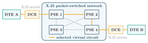
X.25 DTE–DCE access and virtual circuit.
The layer view separates this access path into physical, LAPB link-control, and PLP packet functions at the DTE–DCE interface.
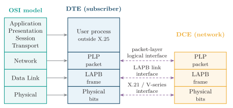
X.25 layer mapping and DTE–DCE interfaces.
With those layer responsibilities identified, the call-flow diagram shows how a switched virtual circuit is established across locally significant logical-channel identifiers.
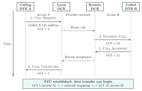
X.25 switched virtual call setup. Solid arrows show PLP packets on the access interfaces; dashed arrows summarise internal network signalling, which X.25 does not prescribe. LCIs 5 and 12 are illustrative local identifiers for the same call.
-
Data and flow control: LAPB uses FCS, acknowledgements and retransmission on one access link. PLP sequences data and maintains a window per VC; RR (Receive Ready) permits more packets, while RNR (Receive Not Ready) pauses them. A link acknowledgement is not end-to-end delivery proof.
-
Clearing: Either DTE sends Clear Request; the peer receives Clear Indication. Each access interface completes Clear Confirmation and releases its channel.
-
Recovery: Reset reinitialises one VC without clearing it; restart affects the whole packet interface, clearing SVCs and resetting PVCs.
Frame Relay
Section titled “Frame Relay”Frame Relay carries variable-length frames over a shared, connection-oriented, data-link-layer WAN. It connects branch routers and LANs, normally through PVCs; SVCs are also supported.
DLCI and Frame Format
Section titled “DLCI and Frame Format”-
Access: A router or FRAD (Frame Relay access device) encapsulates traffic and connects to provider DCE. LMI (Local Management Interface) reports link/PVC status, not delivery of each data frame.
-
DLCI (Data Link Connection Identifier): A local VC identifier, normally 10 bits in a two-octet address. A switch maps incoming port/DLCI to outgoing port/DLCI; values at opposite endpoints need not match.
-
Forwarding: Check the frame, look up the VC, update the DLCI and FCS if needed, then forward. The destination removes the encapsulation.
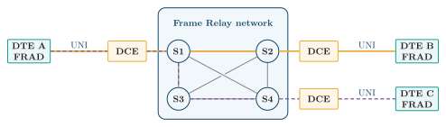
Customer DTE/FRADs connect to provider DCEs; virtual circuits share the Frame Relay network.
The corresponding frame format carries the DLCI together with the FECN, BECN, and DE congestion-control indicators used by that shared network.

Frame Relay frame format.
-
Framing: Flags use
01111110, with bit stuffing between them. The address contains DLCI and control bits; information carries user data; the 16-bit FCS (frame check sequence) detects corruption. -
Error handling: Corrupt frames are discarded. Core data frames have no per-hop sequencing, acknowledgement or retransmission; higher layers recover losses when required.
Congestion Notification
Section titled “Congestion Notification”-
FECN (Forward Explicit Congestion Notification): Set in forward-going frames to notify the receiver of congestion.
-
BECN (Backward Explicit Congestion Notification): Set in reverse-going frames to notify the sender, which can reduce its sending rate.
-
DE (Discard Eligibility): Marks frames for preferential discard, commonly excess traffic; it does not itself prove that congestion has occurred.
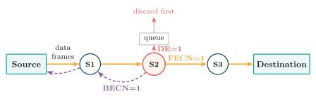
Frame Relay FECN, BECN and DE bits.
CIR and Traffic Contract
Section titled “CIR and Traffic Contract”CIR (committed information rate) is the agreed average rate in bit/s, not the access-line speed or an unconditional delivery guarantee. For measurement interval seconds:
-
Up to : Committed allowance, carried under the service agreement.
-
Additional : Uncommitted excess burst, usually DE-marked and dependent on spare capacity. Traffic beyond may be dropped by policing.
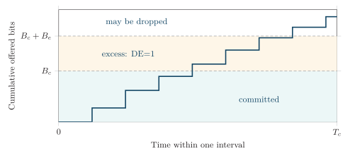
Frame Relay traffic within one interval , with .
X.25 vs Frame Relay
Section titled “X.25 vs Frame Relay”| Basis | X.25 | Frame Relay |
|---|---|---|
| Target links | Error-prone links | Reliable digital links |
| Layer focus | Physical, data link and packet | Data-link service |
| VC identifier | -bit LCI in PLP packets | Usually 10-bit DLCI in frame address |
| Error control | Link retransmission; packet recovery | FCS and discard; higher-layer recovery |
| Flow control | Link and per-VC receive windows | FECN/BECN notification; DE discard priority |
| Trade-off | More recovery overhead and delay | Less overhead; loss and delay still vary |
| Typical use | Legacy public packet-data networks | Legacy branch-office WANs |
Key differences between X.25 and Frame Relay.
Both statistically multiplex virtual circuits over shared links. Modern deployments generally use IP/MPLS, Ethernet or IP VPN services instead.
TCP/IP Protocol Suite
Section titled “TCP/IP Protocol Suite”TCP/IP (Transmission Control Protocol/Internet Protocol) is the practical protocol suite used to interconnect heterogeneous networks and provide end-to-end communication across the Internet.
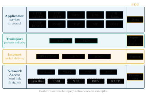
Representative protocols and PDUs in the four-layer TCP/IP architecture.
| Layer | Main function | Protocols | PDU |
|---|---|---|---|
| Application | User network services | HTTP, FTP, SMTP, DNS, SSH, DHCP | Data |
| Transport | End-to-end process communication | TCP, UDP | Segment/datagram |
| Internet | Logical addressing and routing | IP, ICMP, IGMP | Packet |
| Network Access | Local delivery and physical access | Ethernet, Wi-Fi, PPP, ARP | Frame/bits |
TCP/IP layers, functions and PDUs
Application Layer
Section titled “Application Layer”-
User services: HTTP supports web requests and responses, FTP transfers files, and SMTP transfers e-mail. HTTPS protects HTTP traffic using TLS.
-
Support services: DNS resolves names and other resource records; DHCP supplies host configuration; SSH provides secure remote login; SNMP supports network monitoring and management.
-
OSI mapping: Application protocols and supporting software perform functions that OSI separates into application, presentation, and session layers. TCP/IP does not require three distinct upper layers.
-
PDU: An application message or application data, whose format is defined by the application protocol.
Transport Layer
Section titled “Transport Layer”-
Process-to-process delivery: Source and destination ports distinguish transport endpoints, allowing several applications to communicate through the same host.
-
TCP: Establishes a connection and delivers an ordered byte stream. It segments and reassembles the stream, uses sequence numbers, acknowledgements, and retransmission for reliability, and provides receiver flow control and network congestion control. It does not preserve application message boundaries.
-
UDP: Sends independent datagrams and preserves their message boundaries. It provides ports and checksum-based error detection, but no built-in retransmission, ordering, flow control, or congestion control. Applications or protocols above UDP must supply any such functions they require.
-
PDU: A TCP segment or a UDP datagram.
| Feature | TCP | UDP |
|---|---|---|
| Connection | Connection-oriented | Connectionless |
| Delivery | Reliable, ordered byte stream | Datagrams without delivery guarantees |
| Message boundary | Not preserved | Preserved |
| Flow control | Built in | Not built in |
| Congestion control | Built in | Not built in |
| Minimum header | bytes | bytes |
| Common uses | HTTP/1.1 and HTTP/2, FTP, SMTP | DNS, RTP media, QUIC |
TCP versus UDP
Internet Layer
Section titled “Internet Layer”-
IP: Carries packets between hosts across interconnected networks using logical source and destination addresses. Routers select the next hop using the destination address and their forwarding tables. IP itself does not guarantee delivery, order, or recovery from loss.
-
ICMP: Carries error reports and control messages, including destination-unreachable, time-exceeded, and echo request/reply messages.
-
IGMP: Reports IPv4 multicast group membership between hosts and their local multicast routers. IPv6 uses MLD, carried in ICMPv6, for this function.
-
PDU: An IP packet, also called an IP datagram.
Network Access / Link Layer
Section titled “Network Access / Link Layer”-
Local delivery: Encapsulates an IP packet in a frame for the next node on the link, detects frame errors, and controls access to a shared medium where needed.
-
Link technologies: Ethernet and Wi-Fi use MAC addresses; PPP carries packets over a point-to-point link. The four-layer model also includes physical transmission as electrical, optical, or radio signals.
-
ARP: Resolves an on-link IPv4 next-hop address to a link-layer address, such as an Ethernet MAC address. For an off-link destination, a host resolves the gateway’s address, not the remote host’s MAC address.
-
PDU: A frame at the link layer; its bits are encoded into signals for transmission.
Encapsulation and Decapsulation
Section titled “Encapsulation and Decapsulation”-
Sender: TCP or UDP adds a transport header to application data. IP adds an IP header; the link protocol adds its frame header and, where specified, a trailer such as an FCS. The frame is then transmitted as signals.
-
Router: Removes the incoming link encapsulation, processes the IP header, and creates a new frame for the outgoing link. Link-layer addresses can therefore change at each routed hop.
-
Receiver: Checks and removes the link encapsulation, processes the IP header, and passes the transport data to TCP or UDP. The transport protocol delivers the payload to the application identified by the destination port. This upward processing is decapsulation.
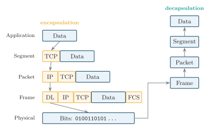
Encapsulation and decapsulation.
| Service | Transport | Port |
|---|---|---|
| HTTP | TCP | 80 |
| HTTPS (HTTP/1.1, HTTP/2) | TCP | 443 |
| HTTPS (HTTP/3) | QUIC over UDP | 443 |
| FTP control | TCP | 21 |
| SSH | TCP | 22 |
| DNS | UDP/TCP | 53 |
| SMTP relay | TCP | 25 |
Common TCP/IP application services and ports
Significance
Section titled “Significance”-
Interoperability: Public protocol specifications allow independently developed hosts, routers, and applications to communicate.
-
Media independence: IP provides a common packet service over different link technologies, so an application need not change when traffic crosses Ethernet, Wi-Fi, or a WAN link.
-
Scalability: Hierarchical addressing and route aggregation allow routers to represent groups of destinations with network prefixes rather than one route per host.
OSI Reference Model
Section titled “OSI Reference Model”The OSI (Open Systems Interconnection) reference model is a seven-layer conceptual framework developed by ISO to standardise how computer and telecommunication systems communicate over a network.
-
Layered services: Each layer uses the services below it and provides services to the layer above. Peer entities follow a protocol, while adjacent layers interact through defined service interfaces.
-
Modularity: A layer’s implementation can change without redesigning higher layers, provided its service interface is preserved.
-
Design and troubleshooting: The model separates problems such as missing physical signals, damaged link frames, incorrect network routes, and failed transport connections. It is a reference framework, not the Internet’s deployed protocol suite.
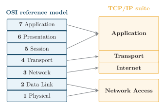
OSI and TCP/IP layer mapping.
Layer Functions and PDUs
Section titled “Layer Functions and PDUs”-
Layer 7, Application: Provides network services to application processes, such as file transfer, messaging, and directory access. HTTP, FTP, SMTP, and DNS perform application-layer functions in TCP/IP.
-
Layer 6, Presentation: Makes data representation understandable to the peer, including syntax and character-encoding conversion, compression/decompression, and encryption/decryption.
-
Layer 5, Session: Establishes, manages, and terminates dialogues. It coordinates who may transmit and can provide synchronisation checkpoints for resuming an interrupted exchange.
-
Layer 4, Transport: Provides end-to-end communication between processes, including segmentation and reassembly, multiplexing, and reliability or flow control where the selected service provides them. TCP and UDP offer different transport services in TCP/IP.
-
Layer 3, Network: Uses logical addresses and routing information to forward packets across multiple networks and select paths to destination hosts.
-
Layer 2, Data Link: Frames data for delivery across one link, detects transmission errors, and manages medium access where required. Some link protocols also provide acknowledgements and retransmission.
-
Layer 1, Physical: Defines signal encoding, bit timing, data rate, media, connectors, and electrical or optical characteristics. It transmits bits without interpreting frames, addresses, or routes.
| L | Name | Main responsibility | PDU |
|---|---|---|---|
| Application | Network services to applications | Data | |
| Presentation | Translation, encryption, compression | Data | |
| Session | Session and dialog management | Data | |
| Transport | End-to-end process delivery; service-dependent reliability | Segment/datagram | |
| Network | Routing and logical addressing | Packet | |
| Data Link | Framing and node-to-node delivery | Frame | |
| Physical | Transmission of raw bits | Bits |
OSI layers and protocol data units
Encapsulation in the OSI Model
Section titled “Encapsulation in the OSI Model”-
Downward path: A layer treats the data received from above as its payload and adds the protocol control information it needs. The familiar TCP/IP PDU sequence mapped to these layers is data segment/datagram packet frame bits.
-
Upward path: The receiving peer interprets the control information and passes the payload to the next layer. The physical layer converts signals to bits; it does not remove a network or transport header.
OSI versus TCP/IP
Section titled “OSI versus TCP/IP”| Feature | OSI model | TCP/IP model |
|---|---|---|
| Nature | Reference model | Practical protocol suite |
| Layers | (or 5) | |
| Developed by | ISO | DARPA / Internet community |
| Usage | Teaching, standardisation | Actual Internet |
| Transport | General model | TCP and UDP |
| Network layer | Connection + connectionless | IP is connectionless |
OSI versus TCP/IP models
The five-layer version of TCP/IP splits Network Access into separate Data Link and Physical layers; the other three layers are unchanged.
Internetworking Devices
Section titled “Internetworking Devices”An internetworking device regenerates, forwards, filters, routes, or translates traffic between links, LAN segments, IP networks, or application endpoints. Its conventional layer is the highest layer whose control information it normally interprets; every device still depends on lower-layer hardware to transmit and receive.
Physical-Layer Devices
Section titled “Physical-Layer Devices”-
Repeater: Receives an attenuated or distorted bit stream, recovers its timing and levels, and transmits a regenerated signal onto another segment. It does not inspect frames or addresses, buffer traffic for congestion control, or choose a destination. In legacy shared Ethernet, the attached segments remain one collision domain.
-
Hub: A multiport repeater that reproduces bits received on one port onto all other ports. All attached stations share bandwidth and one collision domain, so legacy hub Ethernet uses half-duplex operation and carrier-sense/collision-detection procedures. A hub neither learns MAC addresses nor isolates traffic between ports.
-
Modem or media converter: Converts the physical representation of data, such as digital symbols to a carrier waveform or copper signalling to optical signalling. A pure converter changes the medium or signal format without making an IP forwarding decision.
Figure maps these devices and the forwarding devices above them to their predominant operating layers and decision information.

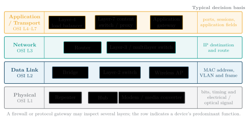
Internetworking devices by predominant layer and decision information.
Data-Link-Layer Devices
Section titled “Data-Link-Layer Devices”-
Bridge: Learns source MAC addresses and their incoming ports. For a known unicast destination it forwards only toward the learned port; it filters a frame whose destination lies on the incoming segment and floods broadcasts, multicasts, and unknown unicasts. Each bridge port separates collision domains, but bridged ports remain in one broadcast domain unless VLANs divide them. Spanning Tree prevents forwarding loops in redundant bridged topologies.
-
Layer-2 switch: A high-port-count, hardware-accelerated multiport bridge. Each switched full-duplex port is its own collision domain, eliminating normal Ethernet collisions, while all ports in one VLAN share that VLAN’s broadcast domain. The switch uses a MAC forwarding table; it does not route between IP subnets unless it also has Layer-3 capability.
-
Wireless access point: Bridges IEEE 802.11 wireless stations to a distribution network such as Ethernet. It manages association and wireless-medium access, but ordinary forwarding remains a Layer-2 function; a home “wireless router” combines this AP with routing, firewall, and often modem functions.
Network-Layer and Multilayer Devices
Section titled “Network-Layer and Multilayer Devices”-
Router: Removes the incoming link framing, examines the destination IP address, selects the longest matching route and next hop, decrements IPv4 TTL or IPv6 Hop Limit, and creates new link-layer framing for the outgoing interface. Routed interfaces separate Layer-2 broadcast domains and normally connect distinct IP subnets.
-
Layer-3 or multilayer switch: Combines Layer-2 switching with hardware-based IP routing, commonly to route between VLANs at LAN speed. Its routing decision is fundamentally the same as a router’s; the distinction usually concerns platform design, interface types, scale, and feature set rather than a different OSI rule.
-
Layer-4 load balancer: Selects a server using network and transport information such as addresses, protocol, ports, and connection state. A Layer-7 content switch, reverse proxy, or application delivery controller can terminate or inspect an application protocol and select a service using fields such as an HTTP host name or path. These commercial labels describe the highest information examined, not new OSI layers.
Gateways and Security Devices
Section titled “Gateways and Security Devices”-
Protocol gateway: Interconnects systems that do not share the same protocol or data representation by terminating one side and creating the corresponding exchange on the other. Examples include an e-mail gateway, a VoIP signalling/media gateway, and an application proxy. Translation may change addressing, message syntax, timing, security, or media encoding, so a gateway may span several layers.
-
Firewall: Enforces security policy. A packet filter uses addresses, protocols, and ports; a stateful firewall also tracks connection state; an application firewall or proxy can inspect application messages. Its permitted traffic may still be routed, bridged, proxied, or translated depending on the implementation.
| Device | Usual basis | Forwarding behavior | Domain effect |
|---|---|---|---|
| Repeater / hub | Signal or bits | Regenerates to one segment or repeats to every other port | Does not separate a legacy shared-Ethernet collision domain |
| Bridge / L2 switch | Destination MAC and VLAN | Filters known local traffic; forwards known remote traffic; floods when required | One collision domain per port; one broadcast domain per VLAN |
| Router / L3 switch | Destination IP prefix and route | Selects a next hop and re-encapsulates the packet for the outgoing link | Separates Layer-2 broadcast domains and IP subnets |
| L4–L7 switch / proxy | Ports, state, or application fields | Selects or proxies a service endpoint according to policy | Often terminates connections; scope depends on deployment |
| Protocol gateway | Protocol semantics and representation | Terminates, translates, and originates unlike protocol exchanges | Joins otherwise incompatible systems; may span several layers |
The decisive progression is signal frame packet session or application message. A higher-layer device can make a more informed decision, but it performs more parsing and usually maintains more state.
Solved Examples
Section titled “Solved Examples”Model Answers
Section titled “Model Answers”Example: Circuit, message and packet switching (10 marks)
Switching transfers information through intermediate nodes. The three methods differ in capacity reservation and the amount of data forwarded as one unit.
-
Circuit switching: Reserves capacity along an end-to-end path before user data is sent.
-
The phases are circuit establishment, data transfer, and release. A reservation may use a recurring time slot or a frequency band on each link.
-
Reserved bandwidth and predictable delay after setup suit continuous traffic, such as a PSTN voice call.
-
A call may be blocked when capacity is unavailable; during an accepted call, idle reserved capacity cannot carry another user’s burst.
-
-
Message switching: Each node stores a complete addressed message and forwards it when an outgoing link is available.
-
No circuit is reserved; messages from different sources share the links and may be prioritised in queues.
-
Every hop needs enough storage for the whole message. Long store-and-forward delays make this unsuitable for real-time voice or video.
-
-
Packet switching: Divides a message into smaller packets with headers, allowing traffic from several sources to interleave on shared links.
-
Datagram networks forward each packet independently; routes and arrival order may differ. Virtual-circuit networks establish forwarding state first and normally deliver packets along the same logical path.
-
Statistical sharing suits bursty data and allows successive links to carry different packets concurrently. Header overhead, queuing delay, jitter, and congestion loss are the costs.
-
| Feature | Circuit | Message | Packet |
|---|---|---|---|
| Capacity | Reserved | Shared | Shared |
| Unit | Continuous stream | Whole message | Packet |
| Node buffering | No whole-message storage | Complete message | Packet-sized units |
| Delay | Predictable after setup | Whole-message reception and queuing | Packet reception and queuing |