I/O Devices and Interfaces
An input device converts a user action or physical quantity into digital data. An output device converts digital results into a form usable by a person or another physical system. An I/O interface connects such a peripheral to the processor and memory system.
Classes of I/O Device
Section titled “Classes of I/O Device”| Device | Input supplied |
|---|---|
| Keyboard | Text, numeric data and commands |
| Mouse or touchpad | Pointing position, motion and button actions |
| Scanner | Printed text or images converted to digital form |
| Microphone | Sampled audio signal |
| Camera or webcam | Still-image and video data |
| Barcode/QR reader | Encoded product, ticket or identity data |
| Sensor | A measured quantity such as temperature, pressure or light |
Input-device examples.
| Device | Output produced |
|---|---|
| Monitor | Visual text, graphics and video |
| Printer | Permanent hard copy |
| Speaker | Audible sound |
| Plotter | Large engineering drawings, plans or maps |
| Actuator | Physical motion or control in an automation system |
Output-device examples.
Devices may also be classified as storage devices (SSD or disk), communication devices (network interface or modem), and control/sensing devices. These classes can overlap: a storage device both accepts output writes and returns input reads.
Functions of an I/O Interface
Section titled “Functions of an I/O Interface”Peripherals differ greatly from a CPU in speed, word format, voltage and protocol. The interface therefore provides:
-
Address decoding: selects the intended device and one of its data, status or control registers.
-
Buffering and speed matching: holds data while a fast bus and a slow peripheral operate at different rates.
-
Format conversion: performs serial/parallel, word-width, coding or electrical-level conversion where required.
-
Control and status: starts an operation and reports ready, busy, completion or error conditions.
-
Synchronization: uses clocking or handshakes so both ends know when data are valid.
The processor commonly sees a data register, a status register and a control register. In memory-mapped I/O these registers occupy normal memory addresses; in isolated or port-mapped I/O they occupy a separate I/O address space and use special instructions or control signals.
Programmed, Interrupt-Driven and DMA I/O
Section titled “Programmed, Interrupt-Driven and DMA I/O”| Method | Operation | Main advantage | Main disadvantage |
|---|---|---|---|
| Programmed I/O | CPU issues a command and repeatedly polls the status register until ready, then transfers each item | Very simple hardware and software flow | Busy waiting wastes CPU time |
| Interrupt-driven I/O | CPU starts the device and does other work; the device interrupts when ready, and an ISR transfers data or records completion | Better CPU utilization for intermittent events | Context-switch and per-interrupt overhead |
| DMA | A DMA controller becomes bus master and transfers a programmed block directly between I/O and memory | High block throughput with little CPU work per item | Additional hardware, arbitration and cache-consistency concerns |
Principal I/O transfer methods.
For programmed I/O, the CPU executes a loop such as “read status; test ready; repeat; read data.” It is suitable for a simple device or a very short operation when waiting costs less than interrupt setup.
For interrupt-driven I/O, the CPU enables the device interrupt and continues another task. On readiness, the interrupt-service routine saves context, identifies/services the device, transfers data or acknowledges the event, clears the request and returns. Excessively frequent interrupts can still consume substantial CPU time.
For direct memory access (DMA), the CPU initializes source or destination address, transfer count, direction and device channel. The DMA controller requests the bus, moves data between the interface and RAM, updates address/count, and interrupts the CPU once the block completes or an error occurs. Cycle stealing takes occasional bus cycles; burst mode holds the bus for several transfers and gives higher throughput but may delay the CPU.
Parallel and Serial Interfaces
Section titled “Parallel and Serial Interfaces”A parallel interface carries several bits at once on separate data conductors. It can transfer a word in one interval on a short link, but uses many pins and suffers inter-wire timing skew at high speed or long distance. A serial interface sends ordered bits over one data path (or a small number of lanes). It uses fewer pins and is easier to route over distance, but one lane needs several bit intervals for a word. High symbol rates and multiple lanes allow modern serial links such as PCIe, USB and SATA to exceed older parallel buses.
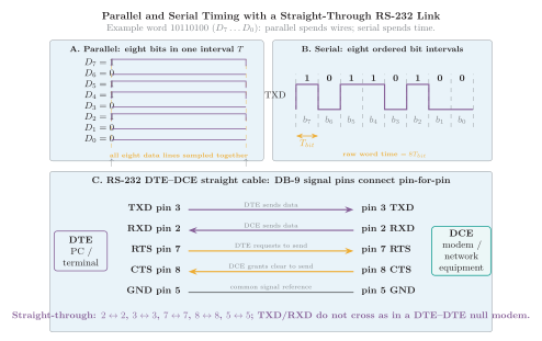
Parallel and serial timing for the word , followed by straight-through RS-232 data, handshake and ground connections.
In the figure, the raw eight-bit word occupies one parallel transfer interval but eight serial bit intervals:
where is bit rate. Real asynchronous serial characters also include framing bits, so their wire time is longer than this raw-data comparison.
RS-232 Interface
Section titled “RS-232 Interface”RS-232 is a single-ended serial electrical and signaling standard originally defined between data terminal equipment (DTE), such as a terminal or PC, and data communication equipment (DCE), such as a modem. It commonly carries asynchronous characters consisting of idle, start, data, optional parity and stop intervals.
| Signal | Pin | Direction at DTE | Function |
|---|---|---|---|
| TXD | Output | Transmitted serial data from DTE to DCE | |
| RXD | Input | Received serial data from DCE to DTE | |
| RTS | Output | Request to send; hardware flow-control request | |
| CTS | Input | Clear to send; DCE permission to transmit | |
| GND | Reference | Common signal reference |
Selected DB-9 RS-232 signals, named from the DTE viewpoint.
A straight-through DTE–DCE cable connects corresponding DB-9 pins (–, –, –, –, –). A DTE–DTE null-modem connection instead crosses data and, when used, handshake signals so that each transmitter reaches the other receiver.
RS-232 uses inverted bipolar levels rather than TTL logic: a mark or logic 1 is negative (typically to ), while a space or logic 0 is positive (typically to ). The region between and is undefined at the receiver. A level translator is therefore required between an RS-232 connector and ordinary low-voltage digital logic. The standard defines the interface, not the meaning of the application data carried within each character.
Quick Review
Section titled “Quick Review”-
Programmed I/O: CPU polls and transfers; simplest but wastes cycles while waiting.
-
Interrupt I/O: device signals readiness, improving CPU utilization at the cost of ISR overhead.
-
DMA: controller transfers blocks directly between I/O and memory and interrupts mainly on completion.
-
Parallel versus serial: parallel spends conductors to move bits together; serial spends bit intervals and uses fewer wires.
-
RS-232: bipolar, inverted, single-ended DTE–DCE serial interface with TXD, RXD and optional hardware handshaking.