Switching and Signalling
Telephony Basics
Section titled “Telephony Basics”Telephony is the transmission and switching of voice signals between subscribers. A telephone network provides call setup, speech-path connection, supervision, charging and call release.

PSTN connection between two subscribers.
| Part | Function |
|---|---|
| Telephone set | Converts speech to electrical signal and back (transducer + hybrid) |
| Local loop | Copper pair between subscriber and exchange |
| Local exchange | Detects dialling, switches calls, provides line supervision |
| Trunk exchange | Connects calls between exchanges |
| Signalling system | Carries control information for setup and release |
| Transmission system | Carries voice channels over copper, microwave, fibre or radio |
Main parts of the PSTN
| Line state | Meaning |
|---|---|
| On-hook | Handset down; loop open; no call current |
| Off-hook | Handset lifted; loop closed; exchange detects demand for service |
| Dialling | Digits sent by pulse or DTMF tone dialling |
| Ringing | Exchange applies ringing voltage to called line |
| Answer | Called party goes off-hook and the speech path is established |
| Release | One or both parties go on-hook; connection is cleared |
Subscriber line states
Switching Functions
Section titled “Switching Functions”A switching system connects an incoming line or trunk to an outgoing one selected from the dialled address and routing rules. It allocates resources during setup, supervises the call, and releases those resources when the call ends.
| Function | Explanation |
|---|---|
| Line scanning | Detect off-hook/on-hook condition of subscriber lines |
| Digit reception | Receive dial pulses or DTMF digits |
| Number analysis | Interpret dialled number and determine route |
| Path selection | Select a free path through the switching network |
| Call setup | Establish connection between calling and called parties |
| Supervision | Monitor answer, busy, release and faults |
| Charging | Record call duration, destination and tariff class |
| Signalling | Exchange control information with other exchanges |
| Maintenance | Alarm, testing, fault localisation, traffic measurement |
Main functions of a switching system
Electromechanical Switching
Section titled “Electromechanical Switching”Electromechanical switches establish speech paths through mechanical contacts operated by electrical signals. Strowger selectors and crossbar matrices are the principal examples.
Strowger Step-by-Step Switch
Section titled “Strowger Step-by-Step Switch”-
Selection: Dial pulses operate stepping magnets. A two-motion selector first moves vertically to a contact-bank level, then rotates to a contact on that level. Intermediate selectors commonly hunt for a free outgoing trunk; final selectors use the remaining digits to select the subscriber.
-
Progressive control: Successive digits establish the path through a train of selectors, tying routing closely to the dialled number and exchange wiring.
-
Limitations: Mechanical movement and contact wear make switching relatively slow and maintenance-intensive. Changing routes or services can require wiring changes.
Crossbar Switch
Section titled “Crossbar Switch”-
Crosspoint operation: Electromagnets operate intersecting select and hold bars to close the contacts connecting a chosen inlet and outlet. The connection is held for the call.
-
Common control: Registers receive digits, and shared control equipment selects an available path before operating the crosspoints. This separates digit reception from mechanical path selection and supports more flexible routing than direct step-by-step control.
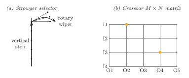
Strowger selector and crossbar switch.
| Feature | Strowger | Crossbar |
|---|---|---|
| Control | Direct (dial pulses) | Common control possible |
| Element | Mechanical selector | Electromagnetic crosspoints |
| Advantage | Removed operator | Faster, more reliable |
| Limitation | Slow, noisy, high maintenance | Many crosspoints for large |
Electronic and SPC Switching
Section titled “Electronic and SPC Switching”Stored Program Control (SPC) switching uses a computer-controlled processor to perform call processing. The switching path may be analog or digital, but control is carried out by stored software instructions.
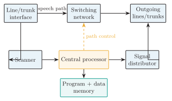
Block diagram of a stored-program-controlled exchange.
| Unit | Function |
|---|---|
| Line/trunk interface | Connects subscriber lines and trunks |
| Scanner | Detects line state changes |
| Distributor | Sends control signals to devices |
| Marker/path control | Selects the switching path |
| Central processor | Executes call-processing programs |
| Memory | Stores programs, subscriber data, routing tables |
| Switching network | Establishes the speech/data path |
| Maintenance terminal | Testing, alarms, operation and maintenance |
Main units of an SPC exchange
-
Centralised SPC: A central control complex performs call processing. It can use duplicated processors for availability; centralised control does not necessarily mean one unprotected CPU.
-
Distributed SPC: Cooperating processors divide control among subsystems. This can improve scalability and fault containment, but requires coordination and recovery from interprocessor failures.
Digital Switching Concepts
Section titled “Digital Switching Concepts”A PCM switch moves samples between input and output time slots and digital highways. Conventional voice produces one 8-bit sample every , giving a channel.
| E1 frame item | Value |
|---|---|
| Number of time slots | 32 |
| Bit rate per time slot | 64 kbit/s |
| Total bit rate | 2.048 Mbit/s |
| Bearer channels in PCM-30 | 30 |
| TS0 | Framing / synchronisation |
| TS16 | Signalling in CAS systems |
Space Switch
Section titled “Space Switch”During each time slot, control memory enables crosspoints connecting selected input highways to output highways. A sample changes highway but retains its slot position; the switch does not buffer it for a different slot. Connections can change from one slot to the next.
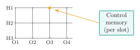
Digital space-switching matrix.
Time Switch
Section titled “Time Switch”A time-slot interchanger writes incoming PCM samples to speech memory and reads them in the order required by the output slots. Control memory stores the address mapping. Buffering changes the slot position and introduces a slot-dependent delay; a sample may be emitted in the following frame when necessary.
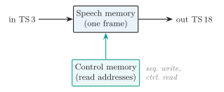
Time-slot interchanger with speech and control memories.
| Mode | Operation |
|---|---|
| Sequential write, controlled read | Store in natural order, read in output order |
| Controlled write, sequential read | Store in output position, read in natural order |
Multistage Digital Switching
Section titled “Multistage Digital Switching”Combining time and space stages provides alternative internal paths without a single enormous switching matrix. Hardware cost and blocking depend on the number of internal highways, available time slots, and route-selection algorithm. The letters TS, ST, TST, and STS give the stage order from input to output.
Time-Space and Space-Time Switching
Section titled “Time-Space and Space-Time Switching”-
TS: The input time stage changes the slot; the following space stage connects the sample to its output highway during that slot.
-
ST: The space stage first selects a highway without changing the slot; the output time stage then moves the sample to its required destination slot.
Time-Space-Time Switching
Section titled “Time-Space-Time Switching”To connect /slot 3 to /slot 18, choose an internal slot, here slot 12, that is free on the relevant input and output paths through the space stage.
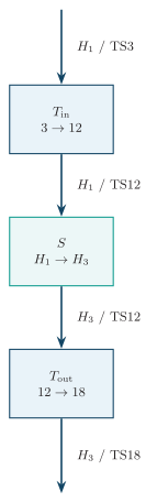
Time-space-time (TST) switching.
-
The input time switch stores the sample received in slot 3 and reads it in internal slot 12.
-
During slot 12, the space switch connects the input highway to the required output highway.
-
The output time switch stores the sample and emits it in slot 18. The mapping repeats each frame until the connection is released.
Space-Time-Space Switching
Section titled “Space-Time-Space Switching”For the same /slot 3 to /slot 18 connection, select an intermediate path whose time switch and space-stage connections are available at the required slots.
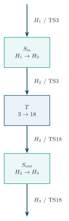
Space-time-space (STS) switching.
-
The first space switch transfers the sample from to during slot 3.
-
The time switch on the intermediate path moves the sample from slot 3 to slot 18.
-
During slot 18, the final space switch connects the intermediate path to .
| Network | Main use | Advantage | Limitation |
|---|---|---|---|
| TS/ST | Small systems | Simple | Limited flexibility/expansion |
| TST | Digital telephone exchanges | Flexible, hardware efficient | Precise timing/control |
| STS | Some multistage designs | Reduces crosspoints | More space-stage hardware |
Comparison of multistage switching networks
Signalling Concepts
Section titled “Signalling Concepts”Signalling is the exchange of control information needed to establish, supervise, charge and release calls.
-
Call information: Includes seizure, calling and called addresses, routing, alerting, answer, busy or congestion indications, and release causes. Answer and release events also drive charging records.
-
Subscriber signalling: Occurs between the user terminal and exchange, for example loop-state changes, dial tone, DTMF digits, and ringing.
-
Inter-exchange signalling: Carries control information between network nodes, for example SS5 tones or SS7 ISUP messages.
| Feature | In-band | Out-of-band |
|---|---|---|
| Placement | Within the bearer signal band | Outside the bearer band or on a separate logical signalling channel |
| Interaction | User signals may interfere with control detection | Control is separated from the speech waveform |
| Example | SS5 tones in a voice circuit | SS7 links; E1 TS16 signalling outside the voice slots |
| Security | Exposed to signalling-like signals on the bearer | Avoids that exposure but still requires access control and message validation |
Signalling System No. 5 (SS5)
Section titled “Signalling System No. 5 (SS5)”SS5 is a legacy international telephone signalling system. It uses in-band line-signalling tones and multifrequency register signals to transfer call-control and address information over the associated speech circuit.
| Feature | SS5 |
|---|---|
| Type | In-band signalling |
| Use | International telephone trunks |
| Medium | Same channel as speech |
| Digit signalling | Multifrequency tones |
| Limitation | Interference/fraud prone, slower setup |
-
Bearer dependence: Tone-based setup occupies the associated circuit and requires reliable tone detection. The speech path can carry signals resembling control tones, creating interference and fraud risks.
-
Limited information: Its signalling vocabulary is less extensible than addressed digital messages, making database services and rich call-control features difficult compared with SS7.
Signalling System No. 7 (SS7)
Section titled “Signalling System No. 7 (SS7)”-
Common-channel transport: SS7 carries addressed control messages on signalling links logically separate from speech channels. One link can control many bearer circuits, and the signalling route need not follow the speech route.
-
Services: ISUP controls circuit calls. Other SS7 applications query databases for intelligent-network services, mobile roaming, and SMS.
| Node | Full form | Function |
|---|---|---|
| SSP | Service Switching Point | Originates/terminates signalling at exchange |
| STP | Signal Transfer Point | Routes SS7 messages |
| SCP | Service Control Point | Service logic and database access, for example intelligent-network number translation |
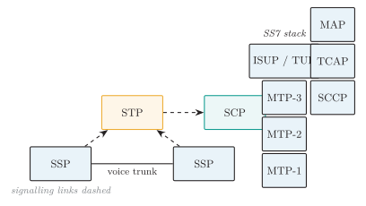
SS7 network architecture and protocol stack.
| Layer/part | Function |
|---|---|
| MTP Level 1 | Physical signalling data link |
| MTP Level 2 | Reliable link transfer, error control |
| MTP Level 3 | Message routing and network management |
| SCCP | Extended addressing, connectionless/connection-oriented service |
| ISUP | Call setup and release for telephone calls |
| TUP | Older telephone user part |
| TCAP | Transaction capabilities for database queries |
| MAP | Mobile application operations, such as location updates and SMS, carried using TCAP |
SS7 protocol stack
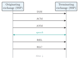
ISUP call establishment and release.
-
IAM (Initial Address Message): The originating exchange selects a circuit and sends the called address and call information toward the destination.
-
ACM (Address Complete Message): The destination side reports that sufficient address information has been received. It may indicate that the called subscriber is free; ACM does not universally mean audible ringing has begun.
-
ANM (Answer Message): Reports answer. Conversation proceeds and answer-based charging normally begins.
-
REL (Release): Requests clearing and includes a cause value.
-
RLC (Release Complete): Confirms release so the circuit can return to the idle pool.
Solved Examples
Section titled “Solved Examples”Model Answers
Section titled “Model Answers”Example: Strowger, crossbar and SPC switching (5–10 marks)
-
Strowger: Dial pulses drive mechanical selectors progressively through a switching train.
-
A two-motion selector moves vertically to a bank level and rotates to a contact; intermediate stages may hunt for a free trunk.
-
It removed the need for an operator to connect each call, but mechanical motion, contact wear, and routing tied to selector wiring made it slow and difficult to modify.
-
-
Crossbar: Select and hold magnets close contacts at the required intersections of a switching matrix.
-
Common registers and markers collect digits and choose a path before operating the switch, decoupling address reception from direct selector movement.
-
A full matrix uses crosspoints. Operation is faster than stepping through many selector positions, but the contacts remain mechanical and large matrices require substantial hardware.
-
-
Stored Program Control: A processor executes software for call processing, routing, charging, and maintenance.
-
Scanners report line state; the processor uses subscriber and route data to allocate a path, control signalling, and update call records through answer and release.
-
Centralised SPC uses a central control complex, often duplicated; distributed SPC divides functions among cooperating processors.
-
SPC describes the control method, not the bearer technology. The controlled switching path can be electromechanical, analog electronic, or digital.
-
| Feature | Strowger | Crossbar | SPC |
|---|---|---|---|
| Control | Direct pulse | Common control | Stored software |
| Path element | Stepping contacts | Crosspoints | Independent of control method |
| Speed | Low | Higher | High |
| Services | Basic | Improved | Rich (forwarding, ID) |
Software control permits routing and service changes without rewiring, supports remote maintenance, and records detailed traffic and billing data. Its availability also depends on software correctness, protected data, reliable power, and tested failover.
Example: TS, ST, TST and STS digital switching (10 marks)
Conventional digital telephone switches move 8-bit PCM samples between highways and time slots. A voice channel supplies one sample every .
-
Time stage (T): Stores samples in speech memory and retrieves them in the required output order using control-memory addresses. It changes slot position; buffering may defer output to the next frame.
-
Space stage (S): Enables a crosspoint between an input and output highway during a slot. It changes highway without changing slot position. A full matrix has crosspoints.
-
TS and ST: TS changes the slot before selecting the output highway. ST selects a highway first and then changes the slot at the output time stage.
-
TST: The input time switch moves a sample to a free internal slot, the space switch transfers it to the chosen output path in that slot, and the output time switch emits it in the destination slot.
-
STS: The first space switch selects an intermediate highway, its time switch changes the slot, and the final space switch selects the destination highway during the new slot.
-
TST example: To connect H1/TS3 to H3/TS18, select internal slot 12 if it is free on both relevant paths. Input T stores the slot-3 sample and reads it at slot 12; S transfers it toward H3; output T stores it and emits it at slot 18. This mapping repeats each frame until release.
| Network | Strength | Limitation |
|---|---|---|
| TS/ST | Simple small system | Limited paths/expansion |
| TST | Many internal slots; efficient | Memory speed, frame control |
| STS | Distributes space paths | More crosspoints/highways |
TST obtains path flexibility by choosing among internal time slots; STS chooses among intermediate highways and time switches. Neither name alone guarantees a nonblocking network: stage dimensions, existing occupancy, and routing determine whether a free internal path exists.
Example: Channel-associated signalling and SS7 (5–10 marks)
Signalling carries seizure, address, routing, alerting, answer, charging-related events, supervision, and release information.
-
CAS: Each bearer circuit has an associated signalling resource. SS5 uses in-band tones on its speech circuit; E1 CAS instead assigns each channel fixed signalling bits in TS16. Thus CAS does not necessarily mean in-band signalling.
-
CCS/SS7: A common signalling network carries addressed messages for many circuits and transactions. SSPs originate or terminate call signalling, STPs route messages, and SCPs execute service logic or query databases.
-
Protocol parts: MTP1 provides the physical link, MTP2 reliable link transfer, and MTP3 routing and network management. ISUP controls circuit calls. SCCP adds addressing and services above MTP; TCAP supports transactions, with applications such as MAP supplying mobile-service operations.
-
ISUP sequence:
-
IAM identifies the selected circuit and transfers address and call information.
-
ACM reports address completion; ANM reports answer and normally starts answer-based charging.
-
REL requests release with a cause; RLC confirms that clearing is complete.
-
-
Benefits and limits: SS7 enables richer call control, database services, roaming, and SMS without carrying control tones through speech channels. Shared signalling requires redundant routes and congestion management; peer screening and access control are still necessary because separation from speech is not a complete security boundary.
| Point | CAS | SS7/CCS |
|---|---|---|
| Association | Fixed signalling resource per bearer | Messages identify circuits or transactions |
| Transport | Bearer tones or assigned signalling bits | Common signalling links |
| Services | Limited per-channel information | Extensible call and database messages |
| Risks | In-band variants exposed to bearer interference | Untrusted signalling peers; shared-link failures |