Digital Baseband Transmission
Baseband Transmission
Section titled “Baseband Transmission”In baseband transmission a digital waveform is sent through a low-pass physical channel without translating it onto a sinusoidal RF carrier. Copper Ethernet, short digital buses and wired PCM links are baseband systems.
A practical baseband link chains: binary source and framing line encoder pulse-shaping filter and line driver physical channel receive/equalization filter timing recovery and decision circuit line decoder.
Why Raw Bits Need Line Coding
Section titled “Why Raw Bits Need Line Coding”An abstract bit sequence has no defined voltage, polarity or transition timing. A line code assigns a physical waveform to each bit (or bit transition). A good line code should provide:
-
Low or zero DC component (vital for transformer-coupled lines).
-
Enough transitions for clock recovery (self-clocking).
-
Limited bandwidth and low high-frequency content.
-
Low baseline wander during long identical runs.
-
Some error indication where possible.
-
Simple encode/decode and robustness to polarity reversal when needed.
No single code optimises every property; the choice is a trade-off.
Line Coding
Section titled “Line Coding”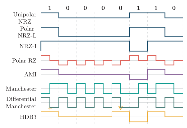
Unipolar NRZ, polar NRZ-L, NRZ-I, polar RZ, AMI, Manchester, Differential Manchester and HDB3 for , time-aligned to one bit grid. NRZ-I uses a start transition for (initial level ); Manchester uses : low-to-high and : high-to-low at mid-bit; Differential Manchester always transitions at mid-bit and uses a start transition for (initial level ). Plain AMI leaves the four-zero run transition-free; HDB3 uses the odd-count substitution with .
| Term | Meaning |
|---|---|
| Bit interval | Duration of one input bit; bit rate |
| Signal element | Shortest waveform element placed on the line |
| Baud / symbol rate | Signal elements per second |
| DC component | Spectral component at |
| Self-clocking | Regular transitions let the receiver recover timing |
| Baseline wander | Drift of the decision reference during long low-frequency runs |
Key line-coding terms.
Binary data does not imply one bit per signal element: Manchester deliberately uses two half-bit elements per bit.
Unipolar and Polar Codes
Section titled “Unipolar and Polar Codes”NRZ-L (Non-Return-to-Zero Level). Absolute level carries the bit (, ); the level is held for the whole bit and never returns to zero. Simplest receiver and lowest bandwidth, but long equal runs have no transitions, data imbalance gives DC/baseline wander, and polarity reversal swaps and .
NRZ-I (Non-Return-to-Zero Inverted). A transition at the bit start means ; no transition means . Information is change, so complete line-polarity inversion does not alter decoding, and a run of s gives regular edges — but a long run of s is still transition-free.
Return-to-Zero (RZ). Polar RZ holds the level for the first half of then returns to ( then ; then ). Guarantees a transition every bit, so timing improves; costs three levels and roughly twice the high-frequency span of NRZ.
Manchester. A compulsory mid-bit transition carries both clock and data; under the common IEEE convention low-to-high and high-to-low at mid-bit. Self-clocking with zero DC per bit; costs about twice the NRZ signalling bandwidth. The convention (0/1 direction) must be stated.
Differential Manchester. There is always a mid-bit transition (clock); data is the presence/absence of a start-of-bit transition ( start transition, none). Self-clocking, zero DC and immune to conductor reversal, at high transition activity.
Bipolar AMI
Section titled “Bipolar AMI”AMI (Alternate Mark Inversion) is a three-level bipolar code: a binary is , and successive binary s (marks) alternate polarity regardless of the zeros between them.
Data: 1 0 1 1 0 0 1 0AMI: ++
Advantages. Alternating marks cancel, so there is no ideal DC and reduced low-frequency energy (transformer-friendly); less transition activity than Manchester; two same-polarity marks form a bipolar violation (BPV) that flags an error or a deliberate substitution; and complete line-polarity reversal does not change mark/space decoding.
Limitation. A long run of zeros gives no pulses, so the clock-recovery circuit can drift and the baseline can wander. HDB3 fixes this for E1.
HDB3 (High-Density Bipolar 3)
Section titled “HDB3 (High-Density Bipolar 3)”HDB3 is an AMI scrambling rule that replaces every run of four zeros by a pattern containing a deliberate bipolar violation, guaranteeing at most three consecutive zero intervals.
| Count since last | Replace | Pulses | Reason |
|---|---|---|---|
| Odd | one violation | Restores even pulse count / resets counter | |
| Even | then (same polarity) | Keeps long-term DC balance |
HDB3 four-zero substitution by pulse-count parity.
Odd-count example. Previous ordinary mark , one mark since last violation, data line with (same polarity as the preceding pulse); ordinary marks then resume alternating from . Even-count example. Previous nonzero pulse , even count: , where the second repeats and is the violation. Decoding: the receiver spots the illegal AMI polarity pattern, replaces the whole or group with four zeros, and resumes ordinary AMI. HDB3 keeps near-zero DC, supplies timing transitions, and is the standard E1/PCM-30 line code (T1 typically uses B8ZS instead).
Line-Code Comparison
Section titled “Line-Code Comparison”Exact occupied bandwidth depends on pulse shape, filtering and the bandwidth definition; the table gives the standard relative comparison used in exams.
| Code | Levels | DC / low-freq | Clock recovery | Rel. BW | Special use |
|---|---|---|---|---|---|
| NRZ-L | Can be significant | Poor on equal runs | Lowest | Simplest links | |
| NRZ-I | Can be significant | Good 1s, poor 0s | Low | Polarity-insensitive | |
| Polar RZ | Lower, not always | Good | High | Simple timing | |
| Manchester | Zero DC | Excellent | NRZ | Classic Ethernet | |
| Diff. Manchester | Zero DC | Excellent | NRZ | Polarity-insensitive | |
| AMI | No ideal DC | Poor on long s | Moderate | BPV error flag | |
| HDB3 | No ideal DC | Good | Moderate | E1 line systems |
Comparison of common baseband line codes.
Selection. NRZ when bandwidth/simplicity dominate and a separate clock/scrambler exists; Manchester when embedded clocking outweighs bandwidth; Differential Manchester when polarity reversal must not matter; AMI for transformer coupling and BPV monitoring with controlled zero runs; HDB3 for self-timed AMI-compatible E1 transport.
Regeneration and Synchronization
Section titled “Regeneration and Synchronization”Digital pulses suffer attenuation, additive noise, dispersion and intersymbol interference (ISI). A regenerative repeater does not merely amplify the analog waveform — it makes a fresh binary decision and launches a clean pulse, so noise does not accumulate indefinitely (provided each hop’s error probability stays low).
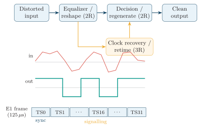
Regenerative repeater: an equalizer reshapes the distorted input, recovered clock retimes the decision, and a decision circuit regenerates clean pulses. Below: noisy received waveform, the regenerated clean output, and an E1 PCM frame (32 timeslots; TS0 sync, TS16 signalling).
Synchronization levels. Bit/clock locates each decision instant (line coding chiefly assists this); word/codeword groups bits into samples/characters; frame locates channel slots/boundaries; and carrier recreates the phase/frequency reference for coherent passband detection.