Communication Fundamentals
Introduction to Communication
Section titled “Introduction to Communication”Communication is the transfer of information from a source to a destination through a physical channel in a form the destination can interpret.
Information may be speech/audio, text/data, image/video, telemetry, or navigation, control and signalling messages. Communication lets us exchange information across distance and time, coordinate people and machines, support safety and air-traffic management, enable telephone, broadcasting, Internet and mobile access, permit remote monitoring/control, and share costly transmission media among many users.
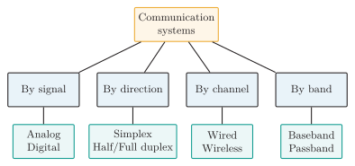
Communication classification by signal type, direction, channel and frequency placement.
By signal representation, analog systems carry continuously varying waveforms while digital systems carry discrete symbols/bits. By medium, guided media are twisted pair, coax, waveguide and fiber; unguided media are ground/sky wave, microwave, satellite and free-space optics. By connection, a link is point-to-point or point-to-multipoint/broadcast.
| Mode | Direction | Example |
|---|---|---|
| Simplex | One direction only | Broadcast radio |
| Half duplex | Both, not simultaneous | Push-to-talk radio |
| Full duplex | Both, simultaneous | Telephone call |
A message may be sent in its original baseband or translated to a passband around a carrier; the chosen frequency depends on channel response, antenna size, propagation, regulation, bandwidth, noise and hardware.
The Communication System
Section titled “The Communication System”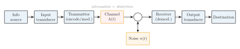
General communication system: the transmitter conditions the message for the channel, an additive-noise node injects , and the receiver recovers the message for the destination.
| Block | Function | Example |
|---|---|---|
| Information source | Produces the message | Speaker, computer, sensor |
| Input transducer | Physical quantity electrical signal | Microphone, camera |
| Transmitter | Codes, modulates, up-converts, amplifies | Mod., mixer, PA |
| Channel | Carries signal; adds loss/distortion | Fiber, copper, air |
| Noise/interference | Adds unwanted random/deterministic energy | Thermal, adjacent Tx |
| Receiver | Selects, amplifies, recovers message | Front end, demod. |
| Output transducer | Electrical physical form | Speaker, display |
| Destination | Final user or machine | Listener, computer |
Main blocks of a communication system.
A convenient channel model is , with transmitted, the channel impulse response, additive noise and received. The transmitter performs source/channel coding, modulation or line coding, multiplexing, frequency conversion, filtering and power amplification. It also provides impedance matching for efficient power transfer with minimal reflection, then couples the conditioned signal to a cable, optical fiber or antenna. Channel impairments are attenuation, amplitude/phase distortion, noise, interference, fading/multipath and dispersion/ISI. The receiver preselects and matches, low-noise amplifies, down-converts and channel-filters, demodulates/detects, recovers timing/carrier, and decodes with error control.
Analog and Digital Communication
Section titled “Analog and Digital Communication”In analog communication a carrier parameter varies continuously with the message (AM, FM). In digital communication information is mapped to a finite alphabet; an analog source follows sampling quantization encoding digital modulation.
| Feature | Analog | Digital |
|---|---|---|
| Representation | Continuous waveform | Discrete symbols/bits |
| Repeaters | Amplify signal and noise | Regenerate symbol decisions |
| Error control | Limited | Detection, FEC, ARQ |
| Processing | Analog filtering/modulation | Compression, encryption, DSP |
| Multiplexing | FDM common | TDM, statistical, packets |
| Copy/storage | Degrades per copy | Exact below error threshold |
| Bandwidth | Often lower | May be higher (coding) |
| Sync. | Less stringent | Bit/symbol/frame/carrier |
| Impairment | No quantization | Quantization noise |
| Examples | AM/FM radio | PCM, mobile, Wi-Fi, optical |
Analog versus digital communication.
Digital communication gains regeneration, error control, encryption, computer compatibility and flexible software-defined processing, at the cost of A/D–D/A conversion, quantization error, synchronization, often greater bandwidth, and a threshold (abrupt) failure when the bit-error rate becomes excessive; analog quality instead degrades gradually with SNR.
Signal Classification
Section titled “Signal Classification”A signal is a function conveying information about a physical phenomenon, written in continuous time or in discrete time.
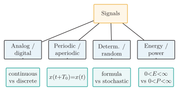
Signal classification by amplitude/time, repetition, predictability and energy measure.
An analog signal has continuous amplitude; a digital signal takes values from a finite set. Discrete time does not imply digital amplitude: sampled-but-unquantized data is discrete-time yet analog-valued. A signal is periodic if a least (integer ) satisfies (), with ; otherwise it is aperiodic. Deterministic signals follow a known formula; random signals (thermal noise, message data) need statistical descriptions.
| Class | Condition | Example |
|---|---|---|
| Energy signal | , | Finite-duration pulse |
| Power signal | , | Nonzero periodic sinusoid |
A nonzero signal cannot be both an energy and a power signal, and some are neither. A baseband signal spans from/near DC to a maximum message frequency (speech, NRZ data); a passband signal occupies a band about a nonzero carrier (AM, FM, PSK, QAM). Modulation translates baseband to passband without ideally altering the information. The carrier is ; amplitude, frequency or phase may be varied, giving AM/ASK, FM/FSK, PM/PSK and (amplitudephase) QAM.
Spectrum and Bandwidth
Section titled “Spectrum and Bandwidth”The spectrum gives amplitude and phase versus frequency; for an aperiodic signal . Bandwidth conventions include absolute, null-to-null, (half-power), occupied (e.g. of power) and channel bandwidth—always state which is meant when comparing modulations.
| Band | Frequency | Typical use |
|---|---|---|
| LF | 30–300 kHz | Long-wave, navigation |
| MF | 0.3 –3 MHz | AM broadcast |
| HF | 3–30 MHz | Shortwave/ionospheric |
| VHF | 30–300 MHz | FM, aviation radio |
| UHF | 0.3 –3 GHz | Mobile, TV, GNSS, Wi-Fi |
| SHF | 3–30 GHz | Microwave, radar, satellite |
| EHF | 30–300 GHz | Millimeter-wave |
Noise in Communication Systems
Section titled “Noise in Communication Systems”Noise is unwanted random electrical energy that obscures or alters the desired signal; structured unwanted energy from another system is interference.
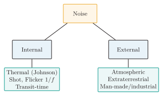
Noise classification into internal (device) and external (environmental) sources.
Their spectra distinguish frequency-independent thermal noise from the low-frequency rise of flicker noise.
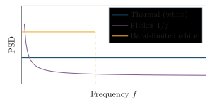
One-sided noise PSD: flat thermal (white) noise, low-frequency flicker noise, and a band-limited white spectrum of bandwidth .
Thermal (Johnson–Nyquist) noise from random carrier motion exists in every resistor above absolute zero and is approximately white over ordinary bands. Shot noise arises from discrete carrier crossing of a junction. Flicker noise (, ) dominates at low frequency. Transit-time noise appears when carrier transit approaches an RF period.
Here , is electron charge and the DC current. External noise: atmospheric (lightning, strongest at low radio frequencies), extraterrestrial (solar/galactic) and industrial/man-made (motors, ignition, switching supplies, power lines, digital electronics). Important system-generated terms are:
-
Intermodulation: nonlinear mixing creates unwanted products, which can fall inside the wanted channel.
-
Crosstalk: capacitive, inductive or radiative coupling leaks another channel into the wanted one, so speech, tones or data patterns from that channel become observable at the receiver.
-
Impulse noise: short, high-amplitude, broad-spectrum disturbances produce clicks or spikes in analog output and bursts of digital bit errors.
-
Quantization noise: finite-level approximation in an ADC produces granular error and raises the conversion noise floor; unlike propagation noise, it is not a physical channel-noise source.
-
Oscillator phase noise: random phase fluctuations spread carrier energy into spectral skirts, degrading close-channel selection and coherent detection.
Together, noise and interference appear as audio hiss/clicks, video speckle, false analog readings, threshold errors and increased BER. Mitigation includes limiting receiver bandwidth, using a low-noise high-gain first stage, shielding/grounding/filtering and separating sources, using balanced transmission and suitable matching, raising power or antenna gain within constraints, and applying coding, interleaving, diversity and robust modulation.
SNR, Noise Figure and Cascaded Receivers
Section titled “SNR, Noise Figure and Cascaded Receivers”Use for a voltage ratio only across equal impedance. An ideal noiseless device has , ; noise temperature is convenient for antennas and very-low-noise front ends.
Channel Capacity
Section titled “Channel Capacity”The Nyquist limit gives the maximum zero-ISI symbol rate ( baud) with each symbol carrying bits; more levels raise the rate but shrink level spacing and increase errors in noise. Shannon–Hartley gives the fundamental noisy-channel limit: rates below allow arbitrarily small error with sufficiently long coding, but it prescribes no particular code and must be the received linear ratio.
| Nyquist | Shannon |
|---|---|
| Ideal noiseless pulse channel | Noisy AWGN channel |
| Depends on levels | Depends on received SNR |
| ISI-free signalling rate | Fundamental info-rate limit |
Modulation and Multiplexing Overview
Section titled “Modulation and Multiplexing Overview”Modulation varies a carrier’s amplitude, frequency or phase according to a message, translating information to a suitable frequency band without ideally changing the information.
Modulation is needed for (1) practical antennas, since and resonant dimensions are fractions of ; (2) channel matching to bandpass/AC-coupled media; (3) frequency allocation and selective tuning; (4) multiplexing; (5) efficient radiation/propagation in a regulated band; and (6) noise/interference strategy, though modulation does not by itself universally reduce noise. For a audio tone radiated directly, and a quarter-wave antenna would be ; at , and quarter-wave .
| Method | Divides | Example |
|---|---|---|
| FDM | Frequency bands | Broadcast, cable TV |
| TDM | Time slots | PCM telephony |
| WDM | Optical wavelengths | Fiber backbone |
| CDM | Spreading codes | CDMA, GNSS |
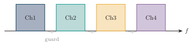
FDM spectrum: baseband channels placed in adjacent frequency bands separated by guard bands.
TDM performs the corresponding separation in time by assigning each source a repeating slot.
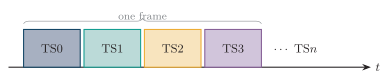
TDM frame: user time slots TS0 – TS repeating within each frame.
Multiplexing combines users onto a medium while modulation maps a message onto a waveform; the two often work together but are not synonymous.