Telecommunications Fundamentals
Evolution of Telecommunications
Section titled “Evolution of Telecommunications”Telecommunication is the transmission and reception of information over distance using electrical, optical, or radio signals. It carries speech, text, data, images, and video.
-
Automation: Automatic exchanges replaced operators who manually connected calls; stored-program control later made call handling and supplementary services software-controlled.
-
Digitisation: PCM coding, regenerative transmission, and digital switching replaced many analog transmission and switching systems.
-
Packet convergence: Voice, video, and data increasingly share IP transport instead of requiring separate service-specific networks.
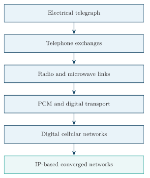
Evolution of telecommunications.
| Date / era | Milestone and significant technology | Importance, including multiplexing |
|---|---|---|
| 1837-1844 | Electrical telegraph and Morse code | Coded pulses provided rapid long-distance text communication. |
| 1874 | Baudot multiplex telegraph | Synchronous time sharing let several telegraph streams use one line, an early form of TDM. |
| 1876-1878 | Telephone and the first commercial manual exchange | Electrical speech enabled real-time conversation; operators established dedicated circuits. |
| 1891-1892 | Strowger automatic exchange | Subscriber dialling introduced automatic electromechanical circuit switching. |
| 1895-1901 | Wireless telegraphy | Radio removed the physical-wire requirement and enabled maritime and long-distance wireless links. |
| 1910s-1930s | Electronic repeaters, carrier telephony and coaxial cable | Amplified long-haul trunks increased range; FDM carried many analog calls in separate frequency bands. |
| 1937-1948 | PCM principle, transistor and information theory | Established the basis for sampled speech, electronic equipment, channel capacity and error-control coding. |
| 1950s-1962 | Terrestrial microwave, communication satellites and T1 PCM | Microwave and Telstar extended long-distance reach; commercial PCM trunks used regenerative transmission and TDM. |
| 1965-1970s | Stored-program control and digital exchanges | Software replaced hard-wired call control; time-slot interchange switched PCM channels efficiently. |
| 1966-1977 | Optical-fibre proposal, low-loss fibre and field deployment | Fibre provided low-loss, high-bandwidth trunks and later became the backbone medium. |
| 1969; 1983 | ARPANET packet switching; TCP/IP adoption | Statistical multiplexing shared links among bursty data flows and interconnected unlike networks. |
| 1979-1991 | Commercial 1G cellular followed by GSM 2G | Cellular frequency reuse enabled mobility; 2G added digital voice, encryption, SMS and FDMA/TDMA access. |
| 1988-1990s | SONET/SDH and WDM/DWDM | Synchronous optical hierarchies simplified transport; WDM carried many wavelengths on one fibre. |
| 1990s-2000s | Internet, VoIP, DSL/cable/FTTH and IP/MPLS | Voice, video and data converged on broadband packet networks with statistical sharing and QoS. |
| 2001; 2009; 2019 | Commercial 3G, 4G LTE and 5G NR | Mobile service evolved from WCDMA packet data to all-IP OFDMA, MIMO, low latency and massive connectivity. |
Analog and Digital Telecommunications
Section titled “Analog and Digital Telecommunications”| Basis | Analog telecommunications | Digital telecommunications |
|---|---|---|
| Information representation | A continuously varying signal parameter represents the message | Discrete symbols represent coded information |
| Repeater action | Amplification increases signal and accumulated noise | Regeneration decides symbols and reconstructs the waveform |
| Noise performance | Noise and distortion accumulate along cascaded links | Decisions tolerate limited noise; excessive impairment produces bit errors |
| Multiplexing | FDM is common in legacy analog trunks | TDM and packet multiplexing are common; digital systems can also use frequency channels |
| Processing | Analog filtering, amplification and modulation | Digital coding, switching, compression and encryption |
| Limitations | Difficult noise removal and less flexible processing | Quantisation, clock recovery, coding overhead and processing delay |
| Examples | Analog telephone loops, AM/FM broadcasting | PCM trunks, Ethernet, digital cellular and IP voice |
Convergence of Voice, Data and Video
Section titled “Convergence of Voice, Data and Video”Convergence carries services such as VoIP, video calls, IPTV, messaging, and web access over a common access, aggregation, and core infrastructure.
-
Source coding: Voice is sampled and coded; video is encoded, usually with compression. Protocols package these streams and computer data into packets.
-
Shared transport: Switches and routers forward packets over the same links using destination addresses or labels. Capacity is shared between active services.
-
Session control: Control systems authenticate users, establish sessions, and apply service policy. Gateways interwork with legacy signalling and media formats.
-
QoS: Classification and scheduling give delay-sensitive traffic suitable treatment; admission control can reject sessions when adequate resources are unavailable.
-
Advantages: Shared links improve utilisation, and a common management platform reduces the need to operate separate networks for each service. Applications can combine voice, video, and data in one session.
-
Constraints: IP alone guarantees neither low delay nor availability. A shared-network failure can interrupt several services at once, so capacity planning, security, path redundancy, and power backup are essential.
Telecommunication Network
Section titled “Telecommunication Network”A telecommunication network is an interconnected system of terminals, transmission links, switching nodes and control systems that transfers information between users or devices.
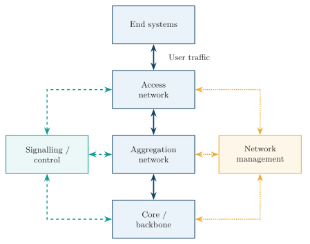
Architecture of a telecommunication network.
Components and Functions
Section titled “Components and Functions”| Component | Function | Examples |
|---|---|---|
| End system | Generates or consumes information and interfaces it to the network | Telephone, computer, mobile handset, sensor |
| Access network | Connects the subscriber to the first provider node | Copper local loop, FTTH, cellular radio access |
| Aggregation network | Combines traffic from many access nodes and transports it toward the core | Metro Ethernet, optical aggregation ring |
| Core or backbone | Carries large traffic volumes between regions, gateways and service networks | IP/MPLS core, optical backbone |
| Switching system | Selects outgoing resources and transfers information toward the destination | Telephone exchange, Ethernet switch, router |
| Transmission system | Carries signals between nodes using a physical medium | Fibre link, microwave hop, copper cable |
| Signalling system | Establishes, supervises, modifies and releases connections or sessions | SS7, SIP, subscriber signalling |
| Network management | Monitors and configures equipment, measures performance and manages faults | OSS, network management system |
One node may perform several functions: a telephone exchange can terminate transmission links, switch bearer channels, and process call signalling.
Access, Aggregation and Core Hierarchy
Section titled “Access, Aggregation and Core Hierarchy”-
Access: Copper loops, FTTH, cellular radio, or Wi-Fi connect subscribers to the first provider node. Coverage and cost per subscriber strongly influence the design.
-
Aggregation: Combines traffic from access nodes onto higher-capacity regional links, applies service policies, and provides protected paths toward the core.
-
Core: Carries high aggregate traffic between regions and service networks. Fast forwarding, alternate routes, and high availability are required because many users depend on each core link.
-
Interconnection: Border routers and gateways exchange traffic with other operators, the Internet, and international networks, applying routing and interworking policies.
A local call may remain within one exchange or region; a long-distance call crosses additional switching and transmission nodes. The route need not traverse every hierarchy level.
Network Planes
Section titled “Network Planes”| Plane | Information carried | Typical functions |
|---|---|---|
| User or bearer plane | Voice samples, application data and video packets | Media transport and forwarding |
| Control plane | Connection, routing and session-control information | Call setup/release, route exchange and resource control |
| Management plane | Configuration, alarms, measurements and administrative information | Fault, configuration, accounting, performance and security management |
Circuit-Switched and Packet-Switched Networks
Section titled “Circuit-Switched and Packet-Switched Networks”-
Circuit switching: Reserves channel capacity along a path before transfer and holds it until release, including periods when the source is silent.
-
Packet switching: Divides information into packets whose headers guide forwarding. Active users share link capacity statistically; packets may queue when their combined arrival rate exceeds the outgoing capacity.
| Basis | Circuit-switched network | Packet-switched network |
|---|---|---|
| Setup | Normally required before user information transfer | Not required for IP datagrams; some packet services establish logical connections |
| Capacity | Reserved for the connection | Shared statistically unless additional reservation mechanisms are used |
| Transfer unit | Continuous stream within the allocated channel | Packet or frame |
| Delay | Predictable after setup, subject to transmission and processing | Variable with queueing, route and network load |
| Bursty traffic | Reserved capacity may remain unused | Capacity can be used by other active sources |
| Impairment under load | New calls may be blocked | Packets may be delayed or discarded |
| Applications | Traditional telephone circuits, leased channels | Internet data, modern voice/video and converged networks |
Transmission Media
Section titled “Transmission Media”The transmission medium carries signal energy from transmitter to receiver.
-
Guided media: Conductors or dielectric waveguides constrain propagation, as in twisted pair, coaxial cable, and optical fibre.
-
Unguided media: Antennas transmit and receive electromagnetic waves through free space, as in terrestrial radio, microwave, and satellite links.
Guided Media
Section titled “Guided Media”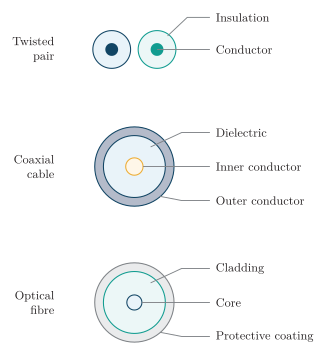
Cross-sections of guided transmission media.
Twisted pair:
-
Construction: Two insulated conductors twisted together.
-
Performance: Balanced signalling and the changing orientation of the pair reduce pickup of external interference and coupling to neighbouring pairs.
-
Limitations: Twisting reduces, but does not eliminate, crosstalk. Attenuation and usable bandwidth depend on cable category, conductor size, frequency and length.
-
Applications: Telephone local loops, DSL and Ethernet.
Coaxial cable:
-
Construction: An inner conductor, dielectric and concentric outer conductor.
-
Performance: The outer conductor provides shielding and a return path, while the geometry determines the characteristic impedance. Coax offers controlled RF performance and good interference rejection.
-
Limitations: Loss increases with frequency, and the cable is bulkier than an individual twisted pair.
-
Applications: Antenna feeders, cable television and RF interconnections.
Optical fibre:
-
Construction: A light-guiding core surrounded by cladding. In the usual step-index description, the core has a higher refractive index than the cladding.
-
Performance: Low attenuation, high capacity, electrical isolation and immunity to electromagnetic interference.
-
Limitations: Dispersion, bending, connector/splice loss and optical receiver sensitivity limit link performance.
-
Applications: FTTH, metropolitan networks, backbones and submarine systems.
Unguided Media
Section titled “Unguided Media”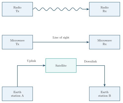
Radio, microwave and satellite links.
Radio links:
-
Operation: Use transmitting and receiving antennas.
-
Propagation: Depending on frequency and environment, propagation can involve line of sight, diffraction, reflection, scattering, ground waves or ionospheric effects.
-
Capabilities: Enable broadcasting and mobility.
-
Limitations: Exposed to interference, fading and spectrum constraints.
Terrestrial microwave links:
-
Configuration: Commonly use high-gain directional antennas between fixed sites.
-
Link requirements: Adequate line of sight and Fresnel-zone clearance are needed.
-
Performance: Directionality permits spatial reuse.
-
Limitations: Terrain, Earth curvature, fading and, at higher frequencies, rain attenuation constrain the link.
-
Applications: Point-to-point backhaul and links across difficult terrain.
Satellite links:
-
Operation: Relay signals between Earth stations through an orbiting transponder or regenerative payload. The uplink reaches the satellite, and the downlink reaches the destination.
-
Coverage: Provide broad coverage and connectivity where terrestrial infrastructure is difficult.
-
Limitations: Path loss, antenna requirements, weather effects in some bands and propagation delay are major constraints.
-
Orbit effects: GEO links have much longer propagation delay than typical terrestrial links; lower orbits reduce path delay but require moving coverage and handover management.
Classification: Microwave and satellite systems both use radio-frequency electromagnetic waves. They are listed separately because their network geometry, equipment and applications differ.
Media Comparison
Section titled “Media Comparison”| Medium | Capacity and interference | Reach and deployment | Typical use |
|---|---|---|---|
| Twisted pair | Rate depends on category and length; balance and twisting reduce interference | Low cable cost; high rates usually require short runs | Telephone access, DSL, LANs |
| Coaxial cable | Wide RF bandwidth and good shielding; loss increases with frequency | Moderate cable and connector cost; amplifiers can extend reach | Antenna feeders, CATV, RF equipment |
| Optical fibre | High capacity, low attenuation, immunity to electromagnetic interference | Long reach; dispersion, civil works, and termination affect design and cost | FTTH, metro, backbone, submarine links |
| Radio access | Spectrum is shared; interference and fading limit capacity | Supports mobility without individual cables to users | Cellular access, broadcasting, WLAN |
| Terrestrial microwave | Directional point-to-point links; link margin accommodates fading | Needs path clearance and suitable sites; tower costs can dominate | Backhaul and regional links |
| Satellite | Shared spectrum, high path loss, band-dependent weather effects | Wide coverage; orbit, terminal cost, and latency determine suitability | Remote access, broadcasting, backup links |
Selection Criteria
Section titled “Selection Criteria”-
Rate and reach: Verify the required data rate over the full link distance, allowing for attenuation, dispersion, interference, receiver sensitivity, and the target BER.
-
Site and service: Check terrain, cable access or radio-path clearance, mobility, maintenance access, security, and required availability. Redundant links may be needed where one failure would interrupt essential service.
-
Cost and regulation: Compare installation and operating costs, including civil works, towers, equipment, and maintenance. Wireless systems also require suitable spectrum and compliance with licensing and power limits.