Communication Circuits
Communication theory defines a waveform; a communication circuit must create or recover it with real devices, biasing, filtering and synchronisation. Answers should label input, output, carrier/LO, filters and feedback paths, then state which unwanted terms are rejected.
Circuit Selection Map
Section titled “Circuit Selection Map”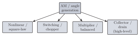
Standard families of AM/DSB generation circuits: nonlinear (square-law), switching, four-quadrant multiplier/balanced and high-level collector/drain modulation.
| Required waveform | Common generator | Common detector |
|---|---|---|
| Standard AM | Low-level multiplier or high-level collector/drain | Diode envelope detector |
| DSB-SC | Balanced/product or ring modulator | Coherent product detector |
| SSB-SC | DSB-SC filter, or phase-shift network | Product detector BFO/carrier recovery |
| FM | VCO/reactance modulator or Armstrong method | Discriminator, ratio detector or PLL |
| PM | Phase modulator | Phase detector/PLL, or discriminator integrator |
| ASK/OOK | Carrier switch/product modulator | Envelope or coherent detector |
| BFSK | VCO or two oscillators | Filter-energy detector, discriminator or correlator |
| BPSK/QPSK/QAM | Balanced I/Q product modulators | Coherent I/Q correlator receiver |
Waveform-to-circuit selection map for generators and detectors.
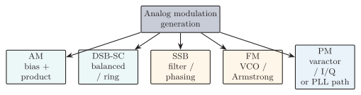
Map of AM, DSB-SC, SSB, FM and direct-PM generation methods. PM may use a varactor phase shifter, vector/IQ modulator or PLL phase path; the exact device implementation varies.
Standard AM Modulators
Section titled “Standard AM Modulators”The required standard-AM output and the no-overmodulation limit are
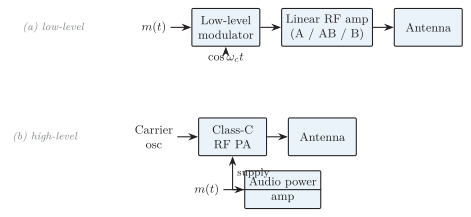
(a) Low-level AM modulates before RF amplification, so every following stage must be linear. (b) High-level AM lets an efficient Class-C final stage run while the audio amplifier varies its collector/drain supply.
Low-Level Modulator
Section titled “Low-Level Modulator”Message and carrier combine at low power; the AM waveform is then amplified to transmitter output power. Methods: diode/transistor square-law modulator, four-quadrant analog multiplier, or a message-controlled variable-gain amplifier. Key requirement: every RF stage after modulation must preserve the envelope, so linear Class A/AB/B amplification is used, which lowers efficiency at high power.
High-Level Modulator
Section titled “High-Level Modulator”The unmodulated carrier is first amplified by an efficient nonlinear stage (commonly Class C) and the audio varies its collector/drain supply. For ideal sinusoidal collector/plate modulation the audio stage must supply about half the carrier power. Advantages: high RF efficiency, suits high transmitter power. Limitations: needs a high-power audio amplifier and a modulation transformer or supply modulator.
| Feature | Low-level AM | High-level AM |
|---|---|---|
| Modulation point | Before RF power amp | At final RF power stage |
| Message power | Small | High |
| Following RF stages | Must be linear | Final may be Class C |
| Overall efficiency | Lower | Higher |
| Main use | Low/medium power, integrated | High-power broadcast |
Low-level versus high-level AM generation.
DSB-SC Modulators
Section titled “DSB-SC Modulators”A product (balanced) modulator multiplies message and carrier so that the standalone carrier term cancels, leaving only the two sidebands (DSB-SC).
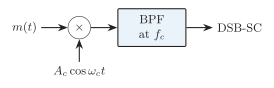
Balanced product modulator: matched branches cancel carrier feedthrough while the cross-products add; a bandpass filter selects the DSB-SC band. Matched-diode, differential/Gilbert and push-pull realizations are common; device mismatch, transformer imbalance and offsets leave finite carrier suppression, quoted in dB against a stated sideband or carrier reference.
Practical balanced implementations use matched diodes, a differential pair or Gilbert-cell multiplier, or two amplitude modulators in push-pull. Their carrier-only terms cancel while the cross-products add. Device mismatch, transformer imbalance and DC offsets leave residual carrier, so carrier suppression in dB must state its reference: normally the wanted sideband level or the corresponding unsuppressed-carrier level.
Diode-Ring (Double-Balanced) Modulator
Section titled “Diode-Ring (Double-Balanced) Modulator”A strong carrier alternately forward-biases opposite diode pairs, reversing the message polarity at the carrier rate (multiplication by a square wave). By symmetry both carrier feedthrough and baseband feedthrough cancel; a bandpass filter selects and rejects the odd switching products A passive ring needs no DC bias, handles a wide dynamic range and is the classic double-balanced mixer.
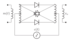
Diode-ring (lattice) modulator: two center-tapped transformers, four diodes and the carrier across the centre taps. Both carrier and message feedthrough cancel, giving DSB-SC after filtering.
SSB Generation Circuits
Section titled “SSB Generation Circuits”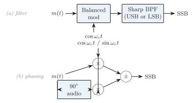
SSB generation. (a) Filter method: DSB-SC then a sharp crystal/mechanical filter selects one sideband. (b) Phasing method: quadrature message and carrier in two product modulators; adding/subtracting cancels one sideband.
Filter method: a balanced modulator makes DSB-SC, a sharp bandpass filter passes only USB or LSB, and linear stages amplify it. For low message frequencies the sidebands crowd near , demanding a highly selective crystal/mechanical filter or generation at a convenient IF followed by mixing.
Phasing method: using -shifted message and carrier,
The challenge is holding an accurate shift and equal amplitude over the whole band. The Weaver method uses two quadrature-mixing stages with low-pass filtering, avoiding a wideband audio Hilbert network and is common in DSP/SDR.
AM Demodulator Circuits
Section titled “AM Demodulator Circuits”Envelope Detector
Section titled “Envelope Detector”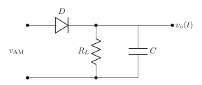
Diode envelope detector: charges near positive carrier peaks; between peaks discharges through following the envelope.
Between peaks . The time constant must exceed a carrier period yet track the fastest envelope:
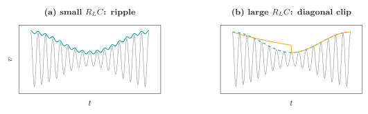
Envelope detection. (a) Too-small leaves carrier ripple. (b) Too-large (orange) cannot follow the falling envelope (green dashed), cutting diagonally across it.
| Distortion | Cause | Remedy |
|---|---|---|
| Carrier ripple | too small | Increase (still track envelope) |
| Diagonal clipping | too large; cannot follow falling envelope | Reduce |
| Negative-peak clipping | AC load DC load (next stage shunts ) | Buffer / raise input impedance |
| Overmodulation | , envelope crosses zero | Reduce modulation depth |
| Threshold distortion | Weak RF near diode drop | Biased/active or synchronous detector |
Envelope-detector distortion mechanisms and remedies.
An envelope detector works only for transmitted-carrier AM with a faithful envelope; it cannot recover DSB-SC or SSB. A square-law detector uses ; the squared term yields a baseband component (good for small signals, distorts as level grows), and a low-pass filter rejects the RF and harmonic products while retaining that baseband term.
Product (Synchronous) Detector
Section titled “Product (Synchronous) Detector”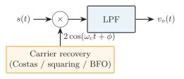
Coherent product detector: multiply by a synchronised local carrier and low-pass filter. Used for DSB-SC and SSB.
Phase error scales the output by (zero at , inverted at ); a frequency error produces audible beat/fading. For SSB a BFO/ reinserted carrier is used and a frequency error shifts every recovered audio tone by . Carrier recovery uses a Costas loop, squaring loop or transmitted pilot.
FM Generation Circuits
Section titled “FM Generation Circuits”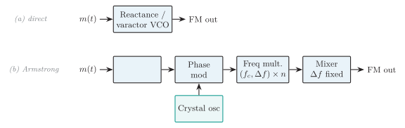
FM generation. (a) Direct: message varies an LC/VCO frequency, large deviation but poorer stability. (b) Indirect (Armstrong): integrate then phase-modulate a crystal carrier; multipliers scale carrier and deviation, whereas the mixer translates carrier without changing deviation.
Direct FM (varactor, VCO, reactance modulator) gives large deviation; a PLL can stabilise the long-term centre frequency. FM is made from PM by integrating first; PM from FM by differentiating first.
Armstrong Indirect FM
Section titled “Armstrong Indirect FM”A crystal oscillator supplies a stable carrier; the message is integrated and applied to a phase modulator to produce narrowband FM. Frequency multipliers then scale both carrier frequency and deviation by their multiplication factor, whereas a mixer translates the carrier to another band without changing the deviation. Armstrong generation therefore gives excellent stability but needs extra stages and careful multiplier/mixer frequency planning.
Direct PM
Section titled “Direct PM”Direct phase modulation may use a message-controlled varactor phase shifter, a vector/IQ modulator that rotates the carrier vector, or a PLL phase-control path. In every case the message controls instantaneous phase rather than directly setting the oscillator frequency.
FM Demodulator Circuits
Section titled “FM Demodulator Circuits”Every FM detector converts frequency deviation to voltage with an ideally linear S-shaped characteristic through :
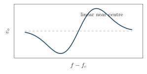
Discriminator S-curve: linear through the centre frequency, saturating away from it.
The detector taxonomy places this slope method alongside balanced, ratio, PLL, and quadrature alternatives.
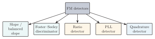
Taxonomy of FM detectors. A balanced slope detector subtracts oppositely detuned responses, extending symmetry and cancelling part of their common amplitude variation.
Slope Detector
Section titled “Slope Detector”Place on the linear slope of a detuned resonant circuit: a frequency change becomes an amplitude change, then an envelope detector recovers the message.
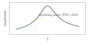
Slope detection: the tuned circuit is used off resonance so its skirt converts frequency deviation into amplitude. It has a narrow linear range and needs a preceding limiter.
A balanced slope detector subtracts two oppositely detuned responses for a wider, more symmetric range. Subtraction also cancels part of the common amplitude variation, but the detector remains AM-sensitive and still needs limiting.
Foster–Seeley and Ratio Detectors
Section titled “Foster–Seeley and Ratio Detectors”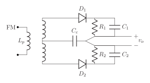
Simplified Foster–Seeley discriminator: a center-tapped double-tuned transformer turns frequency deviation into a phase difference; the two rectified diode voltages are equal at and unequal off centre, and their difference is the audio. A ratio detector uses the same transformer with reversed diode/loading and a large capacitor holding the voltage sum constant, giving inherent AM rejection.
The Foster–Seeley circuit gives high output and very good linearity but responds to amplitude, so a preceding limiter is essential. The ratio detector trades a little linearity for built-in AM rejection and usually needs no separate limiter.
PLL FM Detector
Section titled “PLL FM Detector”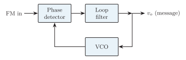
PLL FM demodulator: the VCO tracks the input frequency; within lock the loop-filter control voltage is the recovered message. Its phase comparison is normally amplitude-insensitive, so no separate limiter is normally required.
The PLL gives excellent linearity, amplitude immunity and easy IC integration; the loop bandwidth must follow the highest message frequency and deviation while rejecting noise. Because phase comparison is normally amplitude-insensitive, a PLL FM detector normally needs no separate limiter, although practical input conditioning may still limit or square a weak/noisy signal. A quadrature detector splits the limited FM into direct and frequency-dependent phase-shift paths and multiplies them—also IC-friendly.
| Detector | Principle | Limiter? | Linearity | Feature |
|---|---|---|---|---|
| Slope | Detuned amplitude response | Yes | Poor | Simplest |
| Balanced slope | Difference of two slopes | Yes | Moderate | Symmetric |
| Foster–Seeley | Transformer phase imbalance | Yes | Very good | High output |
| Ratio | Ratio of diode voltages | Usually no | Good | AM rejection |
| PLL | VCO tracks | Normally no | Excellent | IC-friendly |
| Quadrature | Frequency-dependent phase | Limited input | Good | IC-friendly |
Comparison of FM detectors.
Digital Modulator and Demodulator Circuits
Section titled “Digital Modulator and Demodulator Circuits”ASK/OOK: a unipolar bit drives an RF switch/multiplier, ; noncoherent detection uses BPF envelope detector LPF or matched filter a clocked threshold, while coherent detection uses a recovered carrier and correlator. BFSK: bits drive a VCO/DDS or switch between two phase-continuous tones; noncoherent detection uses two bandpass/energy detectors, or a discriminator/PLL converts frequency to voltage. A coherent receiver uses two synchronized correlators and decides for the tone with the larger metric. BPSK: map bits to into a balanced product modulator; a coherent receiver uses carrier recovery (Costas) product detector matched filter zero threshold, with differential encoding resolving the ambiguity.
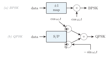
(a) BPSK: antipodal mapping into a balanced modulator. (b) QPSK: a serial-to-parallel mapper drives quadrature product modulators whose sum is the QPSK signal.
For QPSK and QAM, mapped I and Q symbol streams are pulse-shaped before the two product modulators to control occupied bandwidth and intersymbol interference. After coherent I/Q down-conversion, matched filtering and timing recovery, QPSK uses quadrant/sign decisions while QAM selects the nearest allowed constellation point.
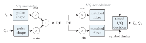
Generic coherent I/Q modem: pulse-shaped branches are quadrature modulated; matched filters and symbol timing feed a clocked decision. QPSK uses quadrant signs, while QAM chooses the nearest allowed constellation point.
QAM adds amplitude levels and needs a linear PA; constant-envelope FSK/MSK tolerates saturated PAs. Essential support blocks are carrier recovery (correct RF phase/frequency for coherent PSK/QAM), symbol-timing recovery (sample each matched-filter output at its optimum instant), frame sync (find word or packet boundaries), AGC (scale I/Q samples into the decision range), and equalisation (compensate channel amplitude/phase distortion and intersymbol interference).
| Metric | Why it matters |
|---|---|
| Carrier / sideband suppression | Wasted power; image and coherent-scheme interference |
| EVM / modulation error | RMS constellation error vs ideal symbols |
| Frequency error / phase noise | Rotation, beat and degraded high-order QAM |
| Linearity (IP3) / PAPR | Intermodulation, spectral regrowth, PA back-off |
| Conversion gain and port isolation | Mixer/modulator level budget; blocks LO/RF/message leakage |
Practical communication-circuit metrics.